Power converting apparatus, grid interconnection apparatus and grid interconnection system

Inactive Publication Date: 2012-06-21
SANYO ELECTRIC CO LTD
View PDF4 Cites 28 Cited by
  • Summary
  • Abstract
  • Description
  • Claims
  • Application Information

AI Technical Summary

Benefits of technology

[0014]According to the feature, occurrence of surge voltage due to a high level of energy remaining in the reactor can be suppressed by turning the first short-circuiting switch off

Problems solved by technology

As a result, there is a problem that, when polarity of output voltage is switched from positive to negative, the current path A is formed by the switching element A and thus the power supply lines are short-circuited.
As a result, there is a problem that, when polarity of output voltage is switched from negative to positive, the current path B is formed by the switching element B and t

Method used


Image

  • Power converting apparatus, grid interconnection apparatus and grid interconnection system
  • Power converting apparatus, grid interconnection apparatus and grid interconnection system
  • Power converting apparatus, grid interconnection apparatus and grid interconnection system

Examples


first embodiment

(1) First Embodiment

[0037]In the first embodiment, (1.1) Configuration of Grid Interconnection Apparatus, (1.2) Operation of Grid Interconnection Apparatus and (1.3) Operation and Effect will be described in this order.

(1.1) Configuration of Grid Interconnection Apparatus

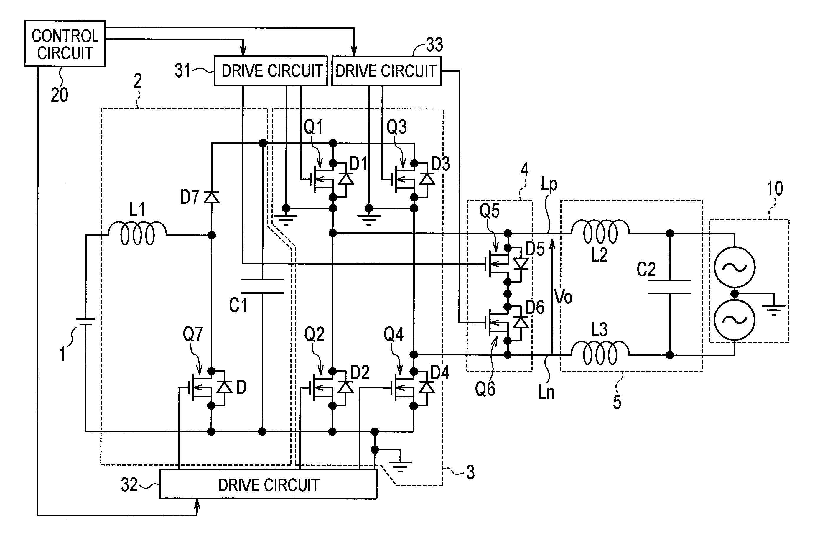
[0038]FIG. 1 is a diagram illustrating a configuration of a grid interconnection system provided with a grid interconnection apparatus according to a first embodiment. In the present embodiment, a transless grid interconnection apparatus will be described as an example. It should be noted that, although the ground (GND) symbols illustrate the same component in FIG. 1, these grounds are not interconnected and are different in potential.

[0039]As illustrated in FIG. 1, the grid interconnection system is provided with a grid interconnection apparatus which is connected between a DC power supply 1 and a distribution system 10. As the DC power supply 1, a solar cell which is one of the distributed DC power supplies may be...

second embodiment

(2) Second Embodiment

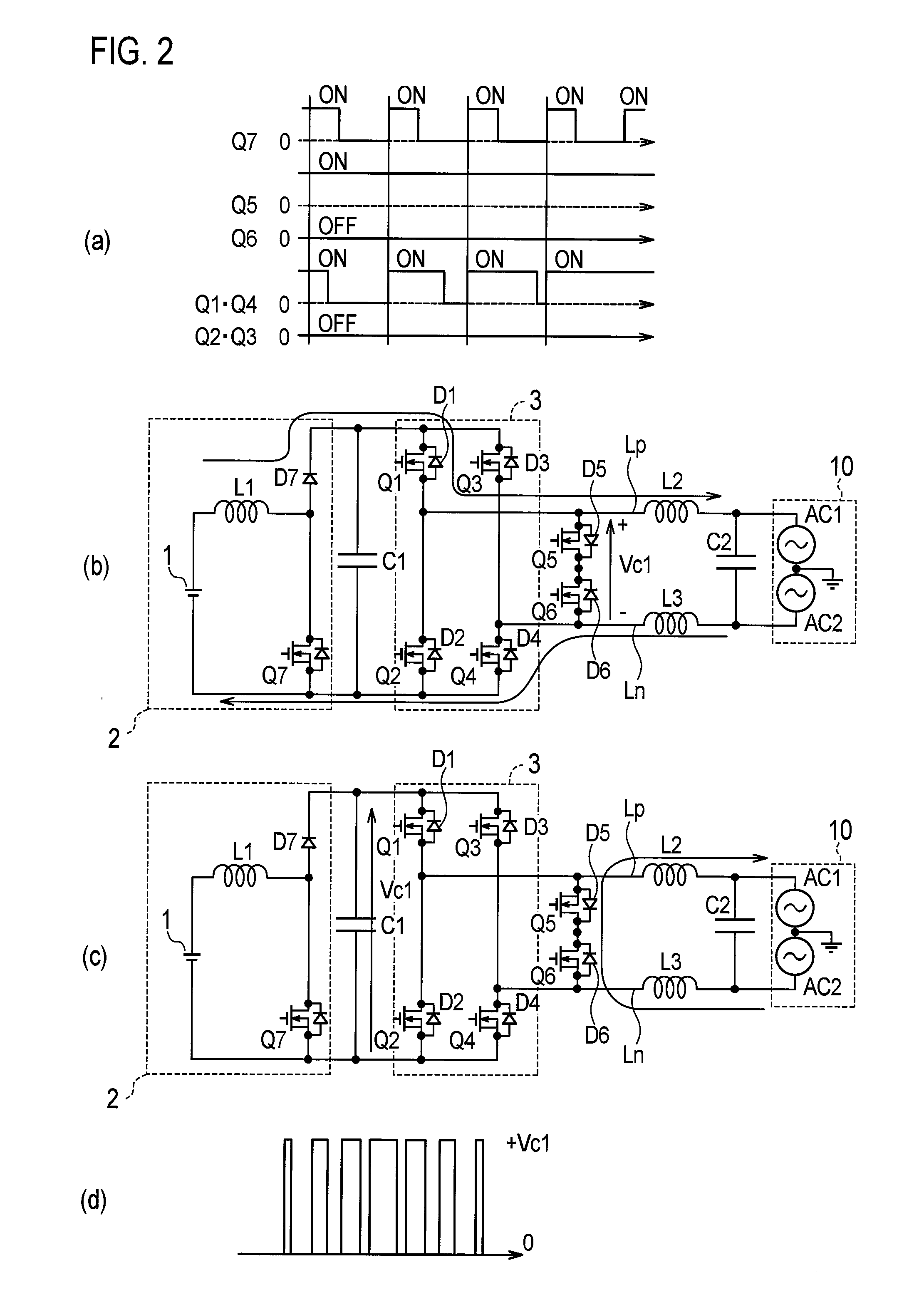
[0075]Next, a second embodiment will be described. In the following second to fifth embodiments, differences from the first embodiment will be described.

[0076]In the first embodiment described above, the state of the switching elements Q5 and Q6 of the output short-circuiting circuit 4 is changed from “on” to “off” at the timing before the zero crossing point. With such control, however, surge voltage may be produced immediately after the change of the state of the switching elements Q5 and Q6 to “off.”

[0077]With reference to FIG. 6, this issue will be described referring to an operation during the change of polarity of the output voltage Vo from positive to negative. FIG. 6(a) is a diagram illustrating a flow of current immediately before the change of the state of the switching element Q5 to “off,”FIG. 6(b) is a diagram illustrating a flow of current immediately after the change of the state of the switching element Q5 to “off,” and FIG. 6(c) is a timing diagr...

third embodiment

(3) Third Embodiment

[0087]Next, a third embodiment will be described. In the first embodiment and the second embodiment described above, since the timing at which the switching operation of the switching element of the inverter circuit 3 is stopped and the timing at which the state of the switching element of the output short-circuiting circuit 4 is changed from “on” to “off” precede the zero crossing point, an amount of the current supplied to the load via the switching element of the output short-circuiting circuit 4 is reduced. However, the reduced amount can be compensated by the condenser C2 of the filter circuit 5 and thus has no problem on a circuit operation.

[0088]Taking advantage of such properties, in the third embodiment, a current detector 11 for detecting an output side current of the filter circuit 5 is provided as illustrated in FIG. 9 and the control circuit 20 controls in accordance with the current detected by the current detector 11. Therefore, favorable control c...


PUM


Abstract

A power converting apparatus is provided with an inverter circuit, an output short-circuiting circuit, and a control circuit. The inverter circuit comprises a first inverter switch and a second inverter switch. The output short-circuiting circuit comprises a first short-circuiting switch configured so as to short-circuit a power supply line that outputs a first polarity voltage, out of a pair of power supply lines, and a second short-circuiting switch configured so as to short-circuit a power supply line that outputs a second polarity voltage, out of the pair of power supply lines. Upon switching the polarity from the first polarity to the second polarity, the control circuit turns off the first short-circuiting switch before the timing whereby the second inverter switch is turned on.

Description

TECHNICAL FIELD[0001]The present invention relates to a power converting apparatus, a grid interconnection apparatus and a grid interconnection system which convert DC voltage from a DC power supply, such as a solar cell and a fuel cell, into AC voltage.BACKGROUND ART[0002]In the related art, this kind of power converting apparatus is provided with a DC-DC converter circuit which steps up DC voltage from DC power supply, an inverter circuit which converts output voltage of the DC-DC converter circuit into AC voltage and outputs the AC voltage to a pair of power supply lines, a filter circuit which removes a high frequency component in output voltage of the inverter circuit, and a control circuit which controls the inverter circuit and the output short-circuiting circuit.[0003]Recently, a circuit system provided with an output short-circuiting circuit configured to short-circuit the pair of power supply lines described above for the improvement in conversion efficiency of the inverte...

Claims


Application Information

Patent Timeline
IPC IPC(8): H02M7/5387
CPCH02J3/381H02M2001/007H02M7/48H02M1/126H02M1/38H02M7/5387H02M7/5395H02M1/0048H02M1/007Y02B70/10
Inventor ESAKA, KOICHIROITOH, KAZUO
Owner SANYO ELECTRIC CO LTD
Why Eureka
Try Eureka