Method and arrangement for receiving an optical input signal and transmitting an optical output signal

Active Publication Date: 2012-06-21
TELEFON AB LM ERICSSON (PUBL)
View PDF4 Cites 5 Cited by
  • Summary
  • Abstract
  • Description
  • Claims
  • Application Information

AI Technical Summary

Benefits of technology

[0013]A further advantage of embodiments of the present invention is that it enables large electric bandwidth and high optical extinction ratio.
[0014]Another advantage of embodiments of the present invention is that it increases robustness against RBS, Rayleigh Backscattering, thanks to saturation in the transceiver unit.
[0015]A further advantage of embodiments of the present invention is increased power budget due to saturation in the transceiver unit.
[0016]Yet a further advantage of embodiments

Problems solved by technology

For some solutions available today it is necessary with tunable elements

Method used


Image

  • Method and arrangement for receiving an optical input signal and transmitting an optical output signal
  • Method and arrangement for receiving an optical input signal and transmitting an optical output signal
  • Method and arrangement for receiving an optical input signal and transmitting an optical output signal

Examples


Embodiment Construction

[0026]The present invention will be described more fully hereinafter with reference to the accompanying drawings, in which preferred embodiments of the invention are shown. The invention may, however, be embodied in many different forms and should not be construed as limited to the embodiments set forth herein; rather, these embodiments are provided so that this disclosure will be thorough and complete, and will fully convey the scope of the invention to those skilled in the art. In the drawings, like reference signs refer to like elements.

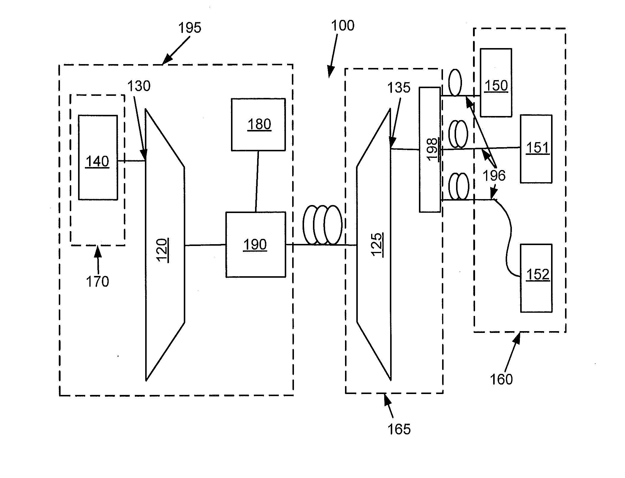
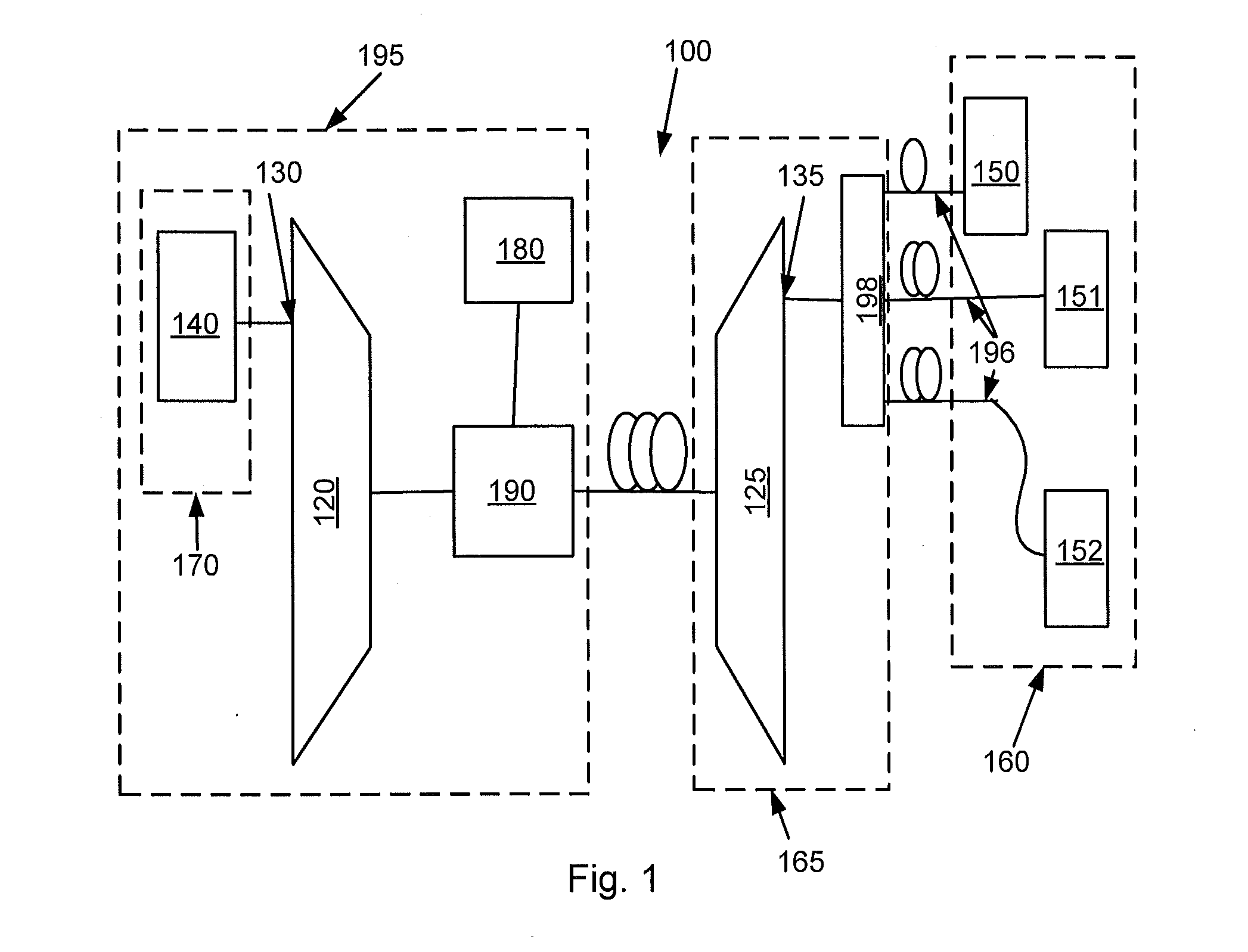
[0027]FIG. 1 is a schematic block diagram of system 100 in which the invention can be implemented. The system 100 comprises several TDM-PON-links (not shown). Each TDM-PON-link has two dedicated wavelengths for bidirectional transmission. By means of cyclic nature of the wavelength multiplexers 120, 125 the wavelength channels are transmitted through a single port 130, 135. The cyclic natures of the multiplexers 120, 125 are based on AWG, Arrayed ...


PUM


Abstract

The present invention relates to a transceiver unit in a PON, Passive Optical Network, for receiving an optical input signal and transmitting an amplitude modulated optical output signal. Further, the present invention relates to a method in a transceiver unit for receiving an optical input signal and transmitting an amplitude modulated optical output signal.

Description

CROSS-REFERENCE TO RELATED APPLICATIONS[0001]This is a 35 USC §111 application claiming priority under 35 USC §119 and §120 to PCT International Application No. PCT / SE2010 / 051436, filed on Dec. 20, 2010, the disclosure of which is incorporated by reference herein in its entirety.TECHNICAL FIELD[0002]The present invention relates to a method and an arrangement for receiving an optical input signal and transmitting an optical output signal.BACKGROUND[0003]A PON (Passive Optical Network) is a point-to-multipoint optical network architecture. The PON may for instance be a Fiber to the Premises, Fiber to the Curb, Fiber to the Cabinet or Fiber to the Building network. Unpowered optical splitters are used to enable a single optical fiber to serve multiple sites.[0004]A PON consists of an OLT (Optical Line Terminal) at the service provider's CO (Central Office) and a number of ONUs (Optical Network Units) near end users. The PON configuration reduces the number of optical fibers required a...

Claims


Application Information

Patent Timeline
IPC IPC(8): H04J14/02H04B10/00H04B10/2587H04B10/272H04B10/556
CPCH04B10/2587H04B10/272H04B10/54H04J2014/0253H04B10/40H04B10/5561
Inventor URBAN, PATRYK
Owner TELEFON AB LM ERICSSON (PUBL)
Why Eureka
Try Eureka