Flow estimation based on anode pressure response in fuel cell system

a fuel cell and anode pressure technology, applied in the direction of cell components, instruments, electrochemical generators, etc., can solve the problems of large estimation errors and relatively expensive materials

Active Publication Date: 2012-06-21
GM GLOBAL TECH OPERATIONS LLC
View PDF16 Cites 27 Cited by
  • Summary
  • Abstract
  • Description
  • Claims
  • Application Information

AI Technical Summary

Problems solved by technology

MEAs are relatively expensive to manufacture and require certain conditions for effective operation.
For certain known systems, this pre

Method used


Image

  • Flow estimation based on anode pressure response in fuel cell system
  • Flow estimation based on anode pressure response in fuel cell system
  • Flow estimation based on anode pressure response in fuel cell system

Examples


Embodiment Construction

[0014]The following discussion of the embodiments of the invention directed to a method for determining the flow of an anode gas out of an anode sub-system is merely exemplary in nature, and is in no way intended to limit the invention or its applications or uses. Particularly, the method discussed herein determines a flow of an anode gas out of the anode sub-system. However, the method will have application for determining the flow out of other closed systems.

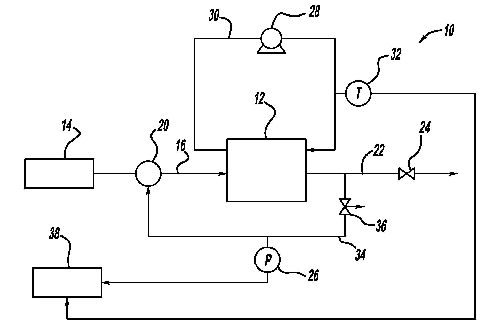
[0015]FIG. 1 is a schematic block diagram of a fuel cell system 10 including a fuel cell stack 12. Hydrogen gas from a high pressure hydrogen gas source 14, such as a tank, is provided to the anode side of the fuel cell stack 12 on an anode input line 16. The hydrogen gas from the source 14 is injected into the stack 12 by an injector 20, where the injector 20 is intended to represent a single injector or a bank of injectors suitable for the purposes described herein. Anode exhaust gas from the fuel cell stack 12 is output on ...


PUM


Abstract

A method for determining the flow of an anode gas out of an anode sub-system. The method includes providing pressure measurements at predetermined sample times over a predetermined sample period and using the pressure measurements to calculate a slope of a line defining a change of the pressure from the beginning of the time period to the end of the time period. The slope of the pressure line is then used in a flow equation to determine the amount of gas that flows out of the anode sub-system, which can be through a valve or by system leaks.

Description

BACKGROUND OF THE INVENTION[0001]1. Field of the Invention[0002]This invention relates generally to a method for determining flow out of a closed system and, more particularly, to a method for determining flow of anode gas out of an anode sub-system in a fuel cell system, where the method determines the slope of a pressure line formed from a plurality of pressure measurements and uses the slope in a flow calculation.[0003]2. Discussion of the Related Art[0004]Hydrogen is a very attractive fuel because it is clean and can be used to efficiently produce electricity in a fuel cell. A hydrogen fuel cell is an electro-chemical device that includes an anode and a cathode with an electrolyte therebetween. The anode receives hydrogen gas and the cathode receives oxygen or air. The hydrogen gas is dissociated at the anode catalyst to generate free protons and electrons. The protons pass through the electrolyte to the cathode. The protons react with the oxygen and the electrons at the cathode...

Claims


Application Information

Patent Timeline
IPC IPC(8): H01M8/06H01M8/24
CPCG01F1/00G01F1/86G01F1/34G01M3/26
Inventor DI FIORE, DANIEL C.BIEBRACH, JAN
Owner GM GLOBAL TECH OPERATIONS LLC
Why Eureka
Try Eureka