Plate glass manufacturing device and plate glass manufacturing method

a technology of plate glass and manufacturing device, which is applied in the direction of glass making apparatus, glass rolling apparatus, manufacturing tools, etc., can solve the problems of reducing the width of the glass ribbon, stably holding steam film, and irregularities of the face of the rollers, so as to achieve high quality

Inactive Publication Date: 2012-06-28
ASAHI GLASS CO LTD
View PDF10 Cites 21 Cited by
  • Summary
  • Abstract
  • Description
  • Claims
  • Application Information

AI Technical Summary

Benefits of technology

[0041]As described above, according to the flat glass production apparatus and the process for producing a flat glass of this invention, molten glass may be formed into a glass ribbon with a desired width and a desired thickness and the equipment may be made compact.
[0042]Furthermore, according to the flat glass production apparatus and the process for producing a flat glass of this invention, a flat glass with a high quality may be produced.

Problems solved by technology

In the production apparatuses of the '949 publication and the '008 publication using the pressure rollers, the rollers disposed above and below the glass ribbon are made to basically oppose linearly to the glass ribbon for rolling out the glass ribbon, and hence, an area for forming the glass ribbon into a thin plate is as small as a linear area, steam generated in this area is instantaneously dispersed, and it is difficult to stably hold a steam film in this area, resulting in a problem that irregularities of the faces of the rollers are transcribed onto the glass ribbon.
When the glass ribbon passing through the glass ribbon forming device is pulled in the carrying direction, the width of the glass ribbon is reduced due to the tension, and hence, there arises a problem that the width of the glass ribbon to be formed is smaller than a desired width and also the thickness is larger than a desired thickness.
A flat glass production apparatus disclosed in the '020 publication, however, has a problem of increase in size of equipment because it needs the forming device of a large scale including a large number of supports, the supply device, the belt conveyor and a plurality of carriage driving rollers.

Method used


Image

  • Plate glass manufacturing device and plate glass manufacturing method
  • Plate glass manufacturing device and plate glass manufacturing method
  • Plate glass manufacturing device and plate glass manufacturing method

Examples


embodiment 1

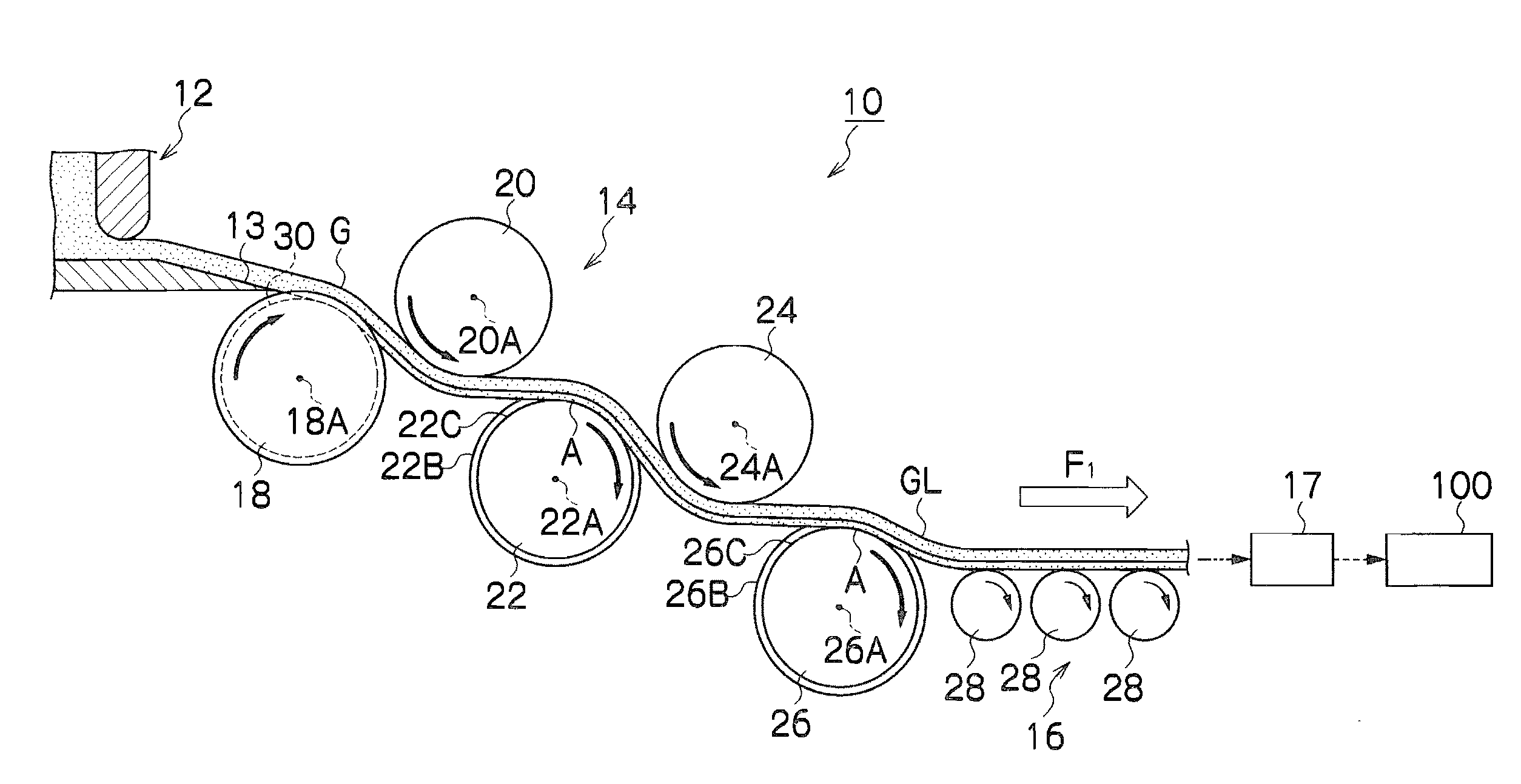
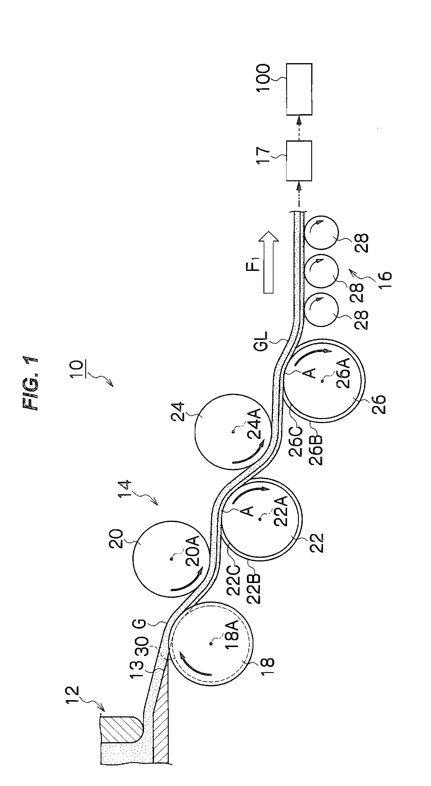
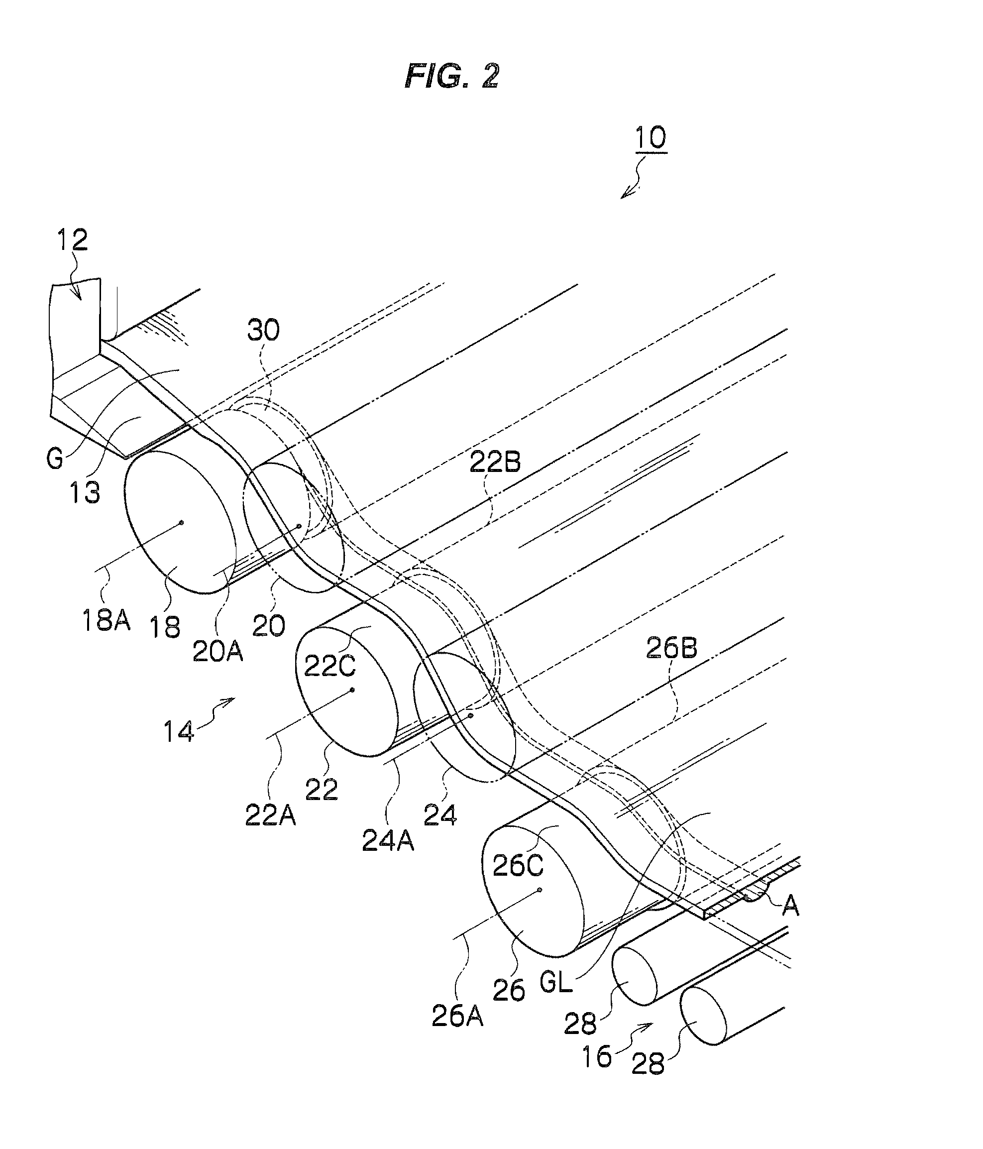
[0054]FIG. 1 is a side view of a flat glass production apparatus 10 used as a reference for describing a flat glass production apparatus , and FIG. 2 is a principal part enlarged view of the flat glass production apparatus 10 of FIG. 1.

[0055]In this production apparatus 10, a glass melting furnace (molten glass supply part) 12, a forming device (forming part) 14 and a roller carriage device (carriage part) 16 are successively arranged along a direction from an upstream side to a downstream side of molten glass G. Furthermore, an annealing furnace 17 for annealing a formed glass ribbon is provided on the downstream side of the roller carriage part 16, and a cutting unit 100 for cutting the annealed glass ribbon is disposed on the downstream side of the annealing furnace. While passing through the annealing furnace 17, the glass ribbon is cooled down to substantially room temperature, and thereafter, the glass ribbon is cut into a prescribed size to be produced into a flat glass. In o...

embodiment 2

[0072]FIG. 3 is a side view of a flat glass production apparatus 40 used as a reference for describing a flat glass production apparatus , and FIG. 4 is a principal part enlarged view of the flat glass production apparatus 40 of FIG. 3. It is noted that like reference numerals are used to refer to like or similar elements used in the flat glass production apparatus 10 of FIGS. 1 and 2 so as to omit the description.

[0073]This production apparatus 40 includes a glass melting furnace 12, a forming device 42, a roller carriage device 16, an annealing furnace 17 and a cutting unit 100.

[0074]Similarly to the forming device 14 of FIG. 1, the forming device 42 includes a plurality of tension rollers 44, 46, 48, 50 and 52, so that a glass ribbon GL falling from a lip face 13 of the glass melting furnace 12 may be stretched and hung successively on the tension rollers 44 to 52.

[0075]At this point, each of the tension rollers 44, 46, 48, 50 and 52 is disposed with their shaft center extending ...

embodiment 3

[0099]FIG. 8 is a principal part enlarged view illustrating the structure of a forming device 82 of a flat glass production apparatus 80 according to In this forming device 82, the tension roller 18 of FIG. 5 is used as an odd-numbered tension roller disposed in the most upstream position, and the tension roller 46 of FIG. 7 is used as an even-numbered tension roller disposed in the most upstream position.

[0100]Specifically, this forming device 82 uses, as the first and second tension rollers disposed in the most upstream position, the tension rollers 18 and 46 having the concave grooves 30 and 54 in their both end portions. When the tension of the glass ribbon GL passing through the forming device 82 is appropriately adjusted, the substantially convex portions A are formed by the concave grooves 30 on the lower face of the glass ribbon GL and the substantially convex portions B are formed by the concave grooves 54. Incidentally, the substantially convex portion formed in each end ...


PUM

PropertyMeasurementUnit
viscosityaaaaaaaaaa
viscosityaaaaaaaaaa
temperatureaaaaaaaaaa

Abstract

A flat glass production apparatus includes a molten glass ribbon supply part supplying a continuous flow of molten glass to a forming part as a glass ribbon of a formable temperature; the forming part including a plurality of tension rollers for forming the glass ribbon of the formable temperature supplied from the molten glass ribbon supply part into a glass ribbon of an unformable temperature; and a carriage part carrying out the glass ribbon of the unformable temperature on a downstream side of the forming part.

Description

TECHNICAL FIELD[0001]The present invention relates to a flat glass production apparatus and a process for producing a flat glass, and more particularly, it relates to a flat glass production apparatus and a process for producing a flat glass in which molten glass is formed into a glass ribbon by using tension rollers.BACKGROUND ART[0002]As processes for forming a glass ribbon, an up draw process, a down draw process, a fusion process and a tin float process are conventionally known, and in addition, a flat glass production apparatus in which molten glass supplied from a molten glass supply part is formed into a glass ribbon by using rollers has been proposed as disclosed in JP-A-2001-180949 (hereinafter referred to as the '949 publication) and JP-A-2006-28008 (hereinafter referred to as the '008 publication). It is noted that a glass ribbon herein means a plate-shaped glass continuous in the form of a ribbon obtained after substantially defining its shape from a state of low viscosi...

Claims


Application Information

Patent Timeline
Patent Type & Authority Applications(United States)
IPC IPC(8): C03B13/16C03B13/04
CPCC03B17/061C03B40/04C03B35/188Y02P40/57C03B17/068C03B18/04
Inventor SHIRAISHI, YOSHIHIROTAKAHASHI, KUNIHISA
Owner ASAHI GLASS CO LTD
Why Eureka
Try Eureka