Hydraulic press unit

a press unit and hydraulic technology, applied in the direction of wrenches, pliers, screwdrivers, etc., can solve the problems of not being easy to replace and not very durable pvc-based dips

Active Publication Date: 2012-06-28
TEXTRON INNOVATIONS +1
View PDF6 Cites 19 Cited by
  • Summary
  • Abstract
  • Description
  • Claims
  • Application Information

AI Technical Summary

Benefits of technology

[0007]According to a first concept of the invention, when the return valve is open, the control valve is acted on by the pressure of the returning hydraulic medium on the inflow side and on the outflow side, the pressure being lower on the inflow side due to throttling. When the return valve is open, the control valve is accordingly exposed on both sides to the pressure of the hydraulic medium in the return flow region, although at different levels of pressure. The pressure difference resulting from the throttling acts in the opening direction of the control valve, and therefore causes, or at least supports, a rapid opening. This effect may be additionally assisted by means of a spring biasing of the control valve into the open position. On the other hand, in preferred embodiments of the subject matter of the invention, this is not the above-mentioned design criterion for an optionally-selected spring biasing. After the return valve opens, this results, practically immediately or possibly even at the same time as the opening of the return valve, in opening of the control valve, and thus in two outflow possibilities for the hydraulic medium. Thus, a desired quicker return travel of the hydraulic piston may clearly be achieved. On the other hand, there are also applications in which the setting is made in such a way that only a very small quantity of the hydraulic medium flows back through the return valve.
[0008]A possible approach, according to which a hydraulic pump is provided, from which a (first) hydraulic-medium flow path leads to the control valve, and a further (second) hydraulic-medium flow path leads directly to the return valve. The hydraulic-medium feed line leading from the hydraulic-medium pump to the control valve and preferably also to a hydraulic cylinder which accommodates the return piston, is also provided directly from the hydraulic-medium pump to the control valve. The mentioned hydraulic-medium flow paths may also partially coincide. It is important that due to the direct connection, the hydraulic medium flows through the feed line to the control valve and to the return valve without first—for example, with reference to the return valve—flowing via the control valve. With regard to the two valves, this provides a parallel connection, starting from the hydraulic-medium pump. The hydraulic-medium inlet (from the pump) and the hydraulic-medium outlet through the (open) return valve are hydraulically located on the same side of the control valve. The connection to the cylinder chamber (movable part) is hydraulically located on the other side of the control valve (or in the bypass for the control valve). Viewed from the movable part, the return valve may be hydraulically situated downstream from the control valve, or, at least additionally, in parallel connection with the control valve. The compact arrangement of the mentioned valves and the hydraulic lines which is thereby made possible is an important aspect.

Problems solved by technology

The prior art insulates the metal valve body with a PVC-based dip, which tends to be inadequate to prevent the passage of heat generated by the high temperature hydraulic fluid.
In addition, the PVC-based dip is not very durable and is not easy to replace if the tool becomes damaged.

Method used


Image

  • Hydraulic press unit
  • Hydraulic press unit
  • Hydraulic press unit

Examples


Embodiment Construction

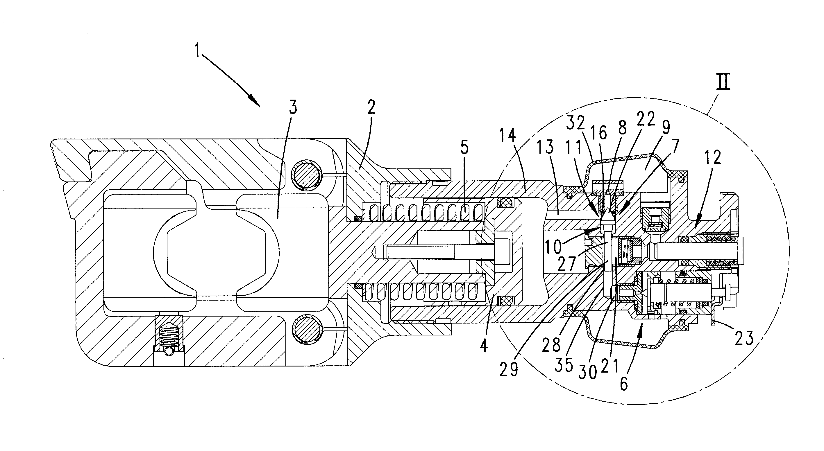
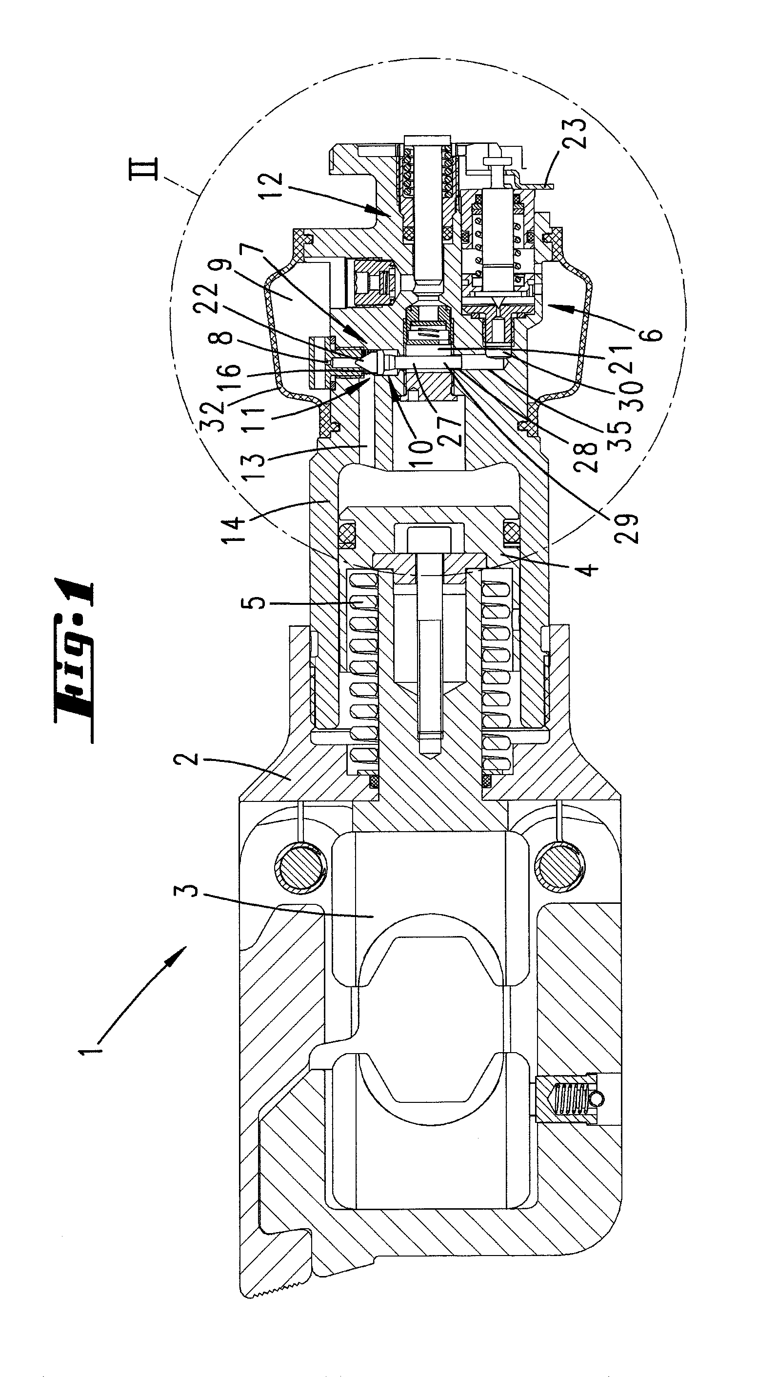
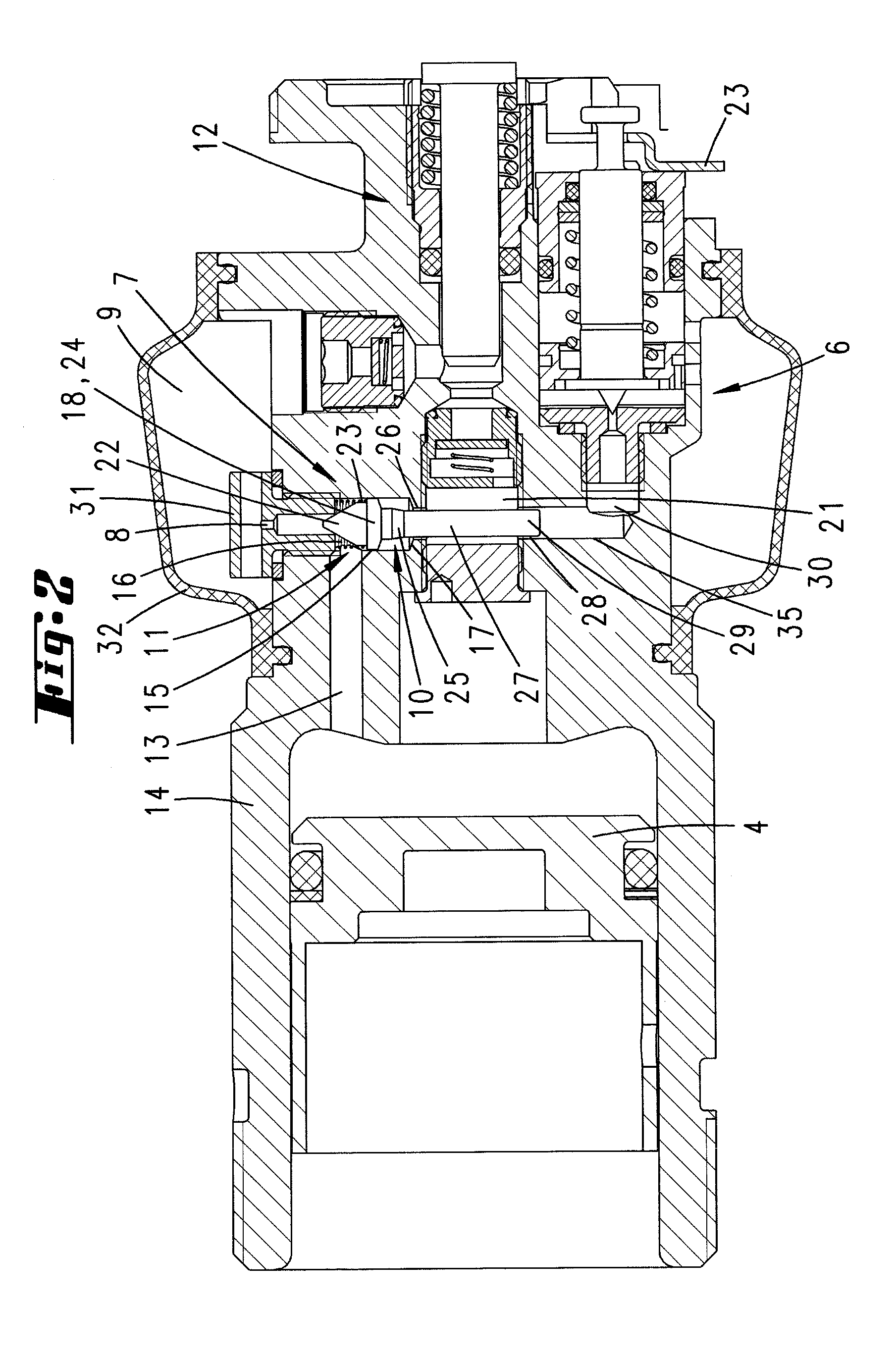
[0029]Illustrated and described, initially with reference to FIG. 1, is a hydraulic press unit having a fixed part 2 and a movable part 3. The movable part 3 is moved relative to the fixed part 2, which may also be regarded as the overall housing, by means of a hydraulic piston 4. The hydraulic piston 4 is movable back into its starting position by means of a return spring 5 and is biased by this spring into the starting position when the piston is not in use. The return movement of the hydraulic piston 4 can be actuated during a pressing operation by activation of a return valve 6. In the exemplary embodiment, this return valve 6 is designed and operates as described in EP 0 944 937 B1. The disclosure content of EP 0 944 937 B1 with regard to the design of this return valve and the corresponding mode of operation is hereby incorporated by reference in the disclosure of the present application, including for the purpose of incorporating one or more features known from said EP 0 944 ...


PUM

PropertyMeasurementUnit
pressureaaaaaaaaaa
pressureaaaaaaaaaa
pressureaaaaaaaaaa

Abstract

A hydraulic press unit has a fixed part and a movable part. The movable part is moved relative to the fixed part by a hydraulic piston and is moved back into a starting position by a return spring. In addition, the return motion is actuatable as a function of a predetermined applied pressure by activation of a return valve. A control valve is provided which, in addition to the return valve, opens a hydraulic-medium outlet when in its open state and has a hydraulic-medium inflow side and a hydraulic-medium outflow side. In order to configure the hydraulic press unit, when the return valve opens, the control valve is acted on by the pressure of the returning hydraulic medium on the inflow and outflow sides, the pressure being lower on the inflow side due to throttling.

Description

[0001]This application is a 35 U.S.C. §371 of PCT / EP2010 / 059356 which has an international filing date of Jul. 1, 2010. This application claims priority to German application No. 102009031678.7 filed on Jul. 2, 2009 and German application No. 102009026273.3 filed on Jul. 29, 2009. Each of these prior applications are incorporated by reference in their entirety.FIELD OF THE INVENTION[0002]The invention relates to a hydraulic press unit having a fixed part and a movable part, the movable part being moved relative to the fixed part by means of a hydraulic piston and being movable back into a starting position by a return spring, and in addition the return motion being actuatable as a function of a predetermined applied pressure by activation of a return valve, and furthermore a control valve being provided which, in addition to the return valve, opens a hydraulic-medium outlet when in its open state and has a hydraulic-medium inflow side and a hydraulic-medium outflow side.BACKGROUND O...

Claims


Application Information

Patent Timeline
Patent Type & Authority Applications(United States)
IPC IPC(8): B25B13/00B25F5/00
CPCB21D22/02B21D39/048B25F5/005B25B27/10B21J15/20F15B15/20
Inventor FRENKEN, EGBERT
Owner TEXTRON INNOVATIONS
Why Eureka
Try Eureka