Enclosure for controlling the environment of optical crystals

a technology of optical crystals and enclosures, applied in the field of illumination, can solve the problems of difficult to provide suitable lasers for high-quality wafer and photomask inspection systems, large lasers generating light energy in the deep ultraviolet range, and high cost of devices with relatively short lifetimes and low average power. , the problem of generating light at wavelengths below 400 nm, and especially below 300 nm,

Active Publication Date: 2012-06-28
KLA TENCOR TECH CORP
View PDF8 Cites 33 Cited by
  • Summary
  • Abstract
  • Description
  • Claims
  • Application Information

AI Technical Summary

Benefits of technology

[0012]According to one aspect of the present design, there is provided an environmentally controlled enclosure comprising a crystal. Multiple crystals may be provided in certain embodiments. The enclosure comprises securing hardware configured to secure the crystal within the enclosure such that temperature changes within the enclosure produce negligible stress on the crystal. The enclosure further includes a window configured to permit light to enter the enclosure and contact the crystal and may include a seal formed between the window and the enclosure.

Problems solved by technology

Providing suitable lasers for high quality wafer and photomask inspection systems is particularly challenging.
Conventional lasers generating light energy in the deep ultraviolet (DUV) range are typically large, expensive devices with relatively short lifetimes and low average power.
Generating light at wavelengths below 400 nm, and especially below 300 nm can be very challenging.
The lifetime, power, and stability of current DUV frequency converted lasers is generally limited by the frequency conversion crystals and conversion schemes, especially those exposed to DUV wavelengths like 355, 266, 213, and 193 nm.
Relatively few nonlinear crystals are capable of efficiently frequency converting light to UV / DUV wavelengths.
Crystal alignment complications can result, and it can be difficult to collect and focus light in such an enclosure.

Method used


Image

  • Enclosure for controlling the environment of optical crystals
  • Enclosure for controlling the environment of optical crystals
  • Enclosure for controlling the environment of optical crystals

Examples


Embodiment Construction

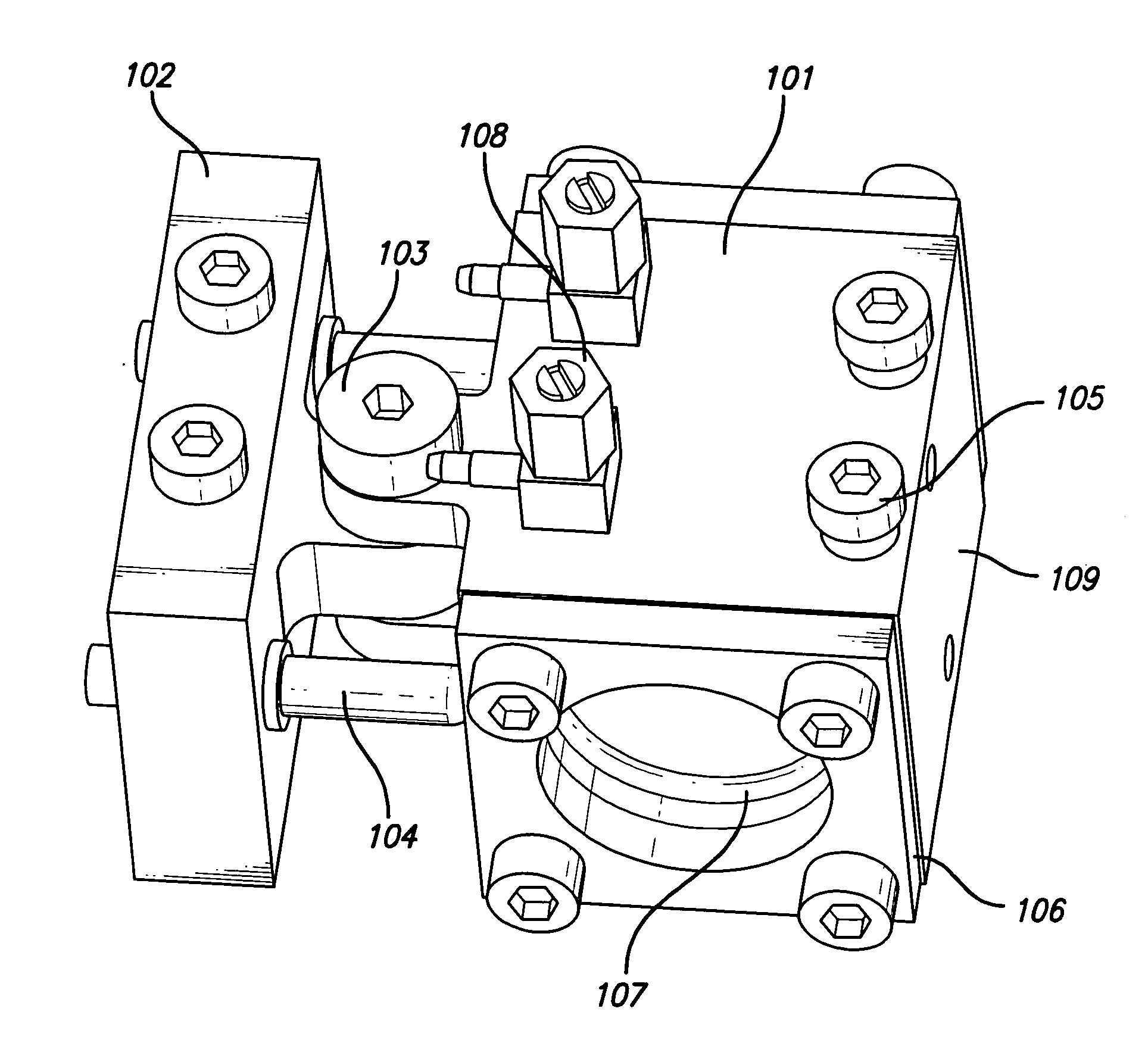
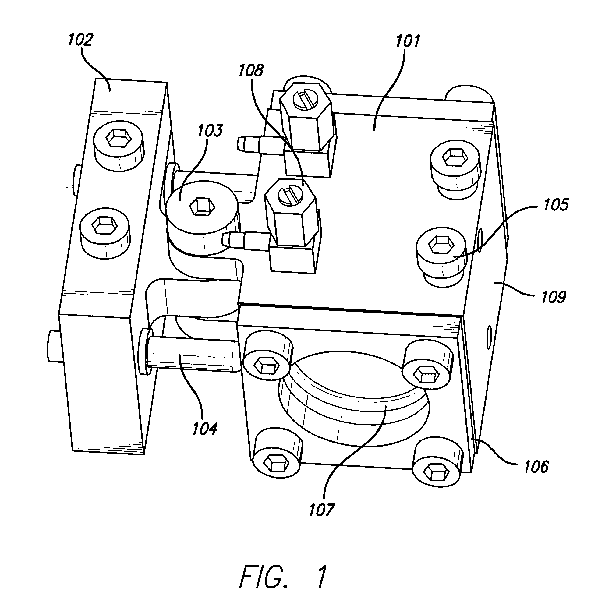
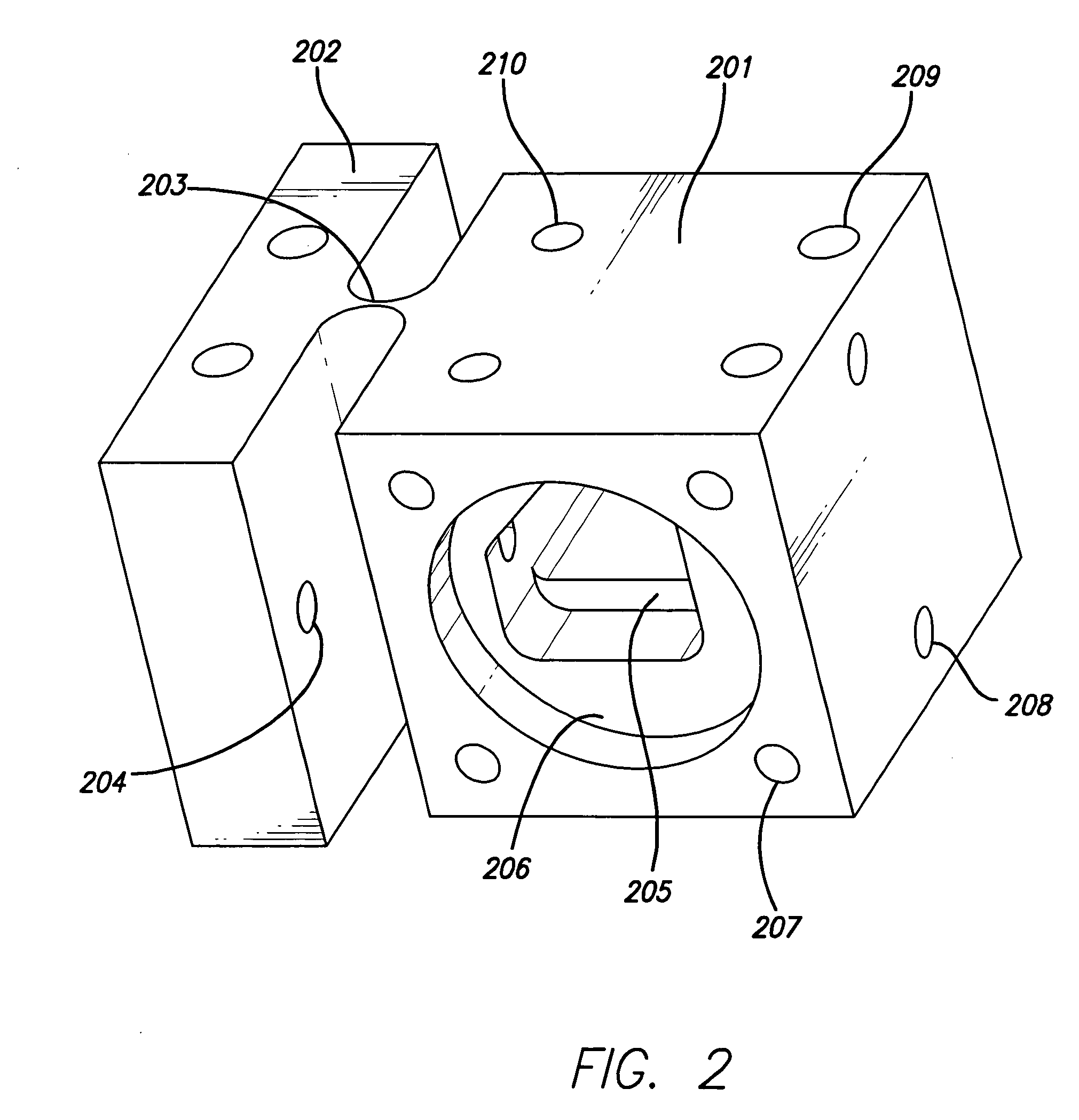
[0034]According to the present design, an enclosure for one or more optical crystals that maintains a desirable environment is provided. The enclosure design allows stable, long lifetime, high power frequency conversion of light to UV / DUV wavelengths. In addition, the same enclosure may be employed to preprocess the crystal(s) before exposing the crystal(s) to frequency conversion light.

[0035]Frequency conversion in this design uses at least one optical crystal within an enclosure, but may also utilize more than one crystal. In the case of multiple crystals, the crystals may be made of the same materials or different materials. The multiple crystals may be used to generate multiple wavelengths or increase the frequency conversion efficiency of a single wavelength.

[0036]Further, the present design may provide an advanced light source having a novel method for producing light energy. The present design may use nonlinear optical crystals within an enclosure, where the enclosure process...


PUM


Abstract

An enclosure that maintains the environment of one or more optical crystals and allows efficient frequency conversion for light at wavelengths at or below 400 nm with minimal stress being placed on the crystals in the presence of varying temperatures. Efficient conversion may include multiple crystals of the same or different materials. Multiple frequency conversion steps may also be employed within a single enclosure. Materials that have been processed specifically to provide increased lifetimes, stability, and damage thresholds over designs previously available are employed. The enclosure allows pre-exposure processing of the crystal(s) such as baking at high temperatures and allowing real time measurement of crystal properties.

Description

[0001]This application claims the benefit of U.S. Provisional Patent Application Ser. No. 61 / 008,260, entitled “Enclosure for Controlling the Environment of Optical Crystals,” inventor J. Joseph Armstrong, filed Dec. 18, 2007, the entirety of which is incorporated herein by reference.BACKGROUND OF THE INVENTION[0002]1. Field of the Invention[0003]The present invention generally relates to illuminators used in conjunction with inspection systems, such as semiconductor wafer inspection systems and photomask inspection systems, and more particularly to a frequency converted light source for use with such inspection systems.[0004]2. Description of the Related Art[0005]The demands of the semiconductor industry for wafer and photomask inspection systems exhibiting high throughput and improvements in resolution are ongoing. Successive generations of such inspection systems tend to achieve higher resolution by illuminating the wafer or reticle using light energy having shorter wavelengths.[...

Claims


Application Information

Patent Timeline
Patent Type & Authority Applications(United States)
IPC IPC(8): B65D81/02B65D81/20B65D81/18B65D25/54
CPCG02F1/3501G02F2001/3505G02F2201/50G02F2203/60Y10T117/10H01S3/042Y10T117/1016Y10T117/1012H01S3/025G02F1/3505
Inventor ARMSTRONG, J. JOSEPH
Owner KLA TENCOR TECH CORP
Why Eureka
Try Eureka