
Multi-purpose pet device

a multi-purpose, pet technology, applied in the field of open pet devices, can solve the problems of increasing psychological stress on patients, obstructing patient treatment, and not being able to be treated, and achieve the effects of convenient switching, convenient introduction to facilities, and improved versatility of open pet devices

Inactive Publication Date: 2012-06-28
NAT INST FOR QUANTUM & RADIOLOGICAL SCI & TECH
View PDF16 Cites 29 Cited by
  • Summary
  • Abstract
  • Description
  • Claims
  • Application Information

AI Technical Summary

Benefits of technology

[0007]The present invention has been achieved in order to solve the foregoing conventional problems. It is thus an object of the present invention to improve the versatility of an open PET apparatus for easier introduction to facilities.
[0008]Specifically, the present invention is directed to allowing changes in the configuration of an open PET device by simple device moving means so that a plurality of single PET devices and a single open PET device can be switched easily. In PET inspections where the open field of view is not needed, the detector rings of the open PET device can be used as respective single PET devices to perform a plurality of PET inspections at the same time. This can increase the use efficiency of the PET facility. This also allows gradual introduction of the open PET device into facilities.
[0009]FIG. 4 shows the concept of an extendable PET device. As shown in FIG. 4(a), a conventional PET device (also referred to as a first PET device) including only one detector ring 31 (also referred to as a first detector ring) is initially introduced. Then, another PET device (also referred to as a second PET device) including only a second detector ring 41 is added so that the two detector rings 31 and 41 can be used as a single open PET device as shown in FIG. 4(b). The detector ring(s) of at least one of the PET devices (in the diagram, the detector ring 41 of the second PET device) can be placed on rails or otherwise configured so as to be movable in the direction of the body axis of the patient 6, the subject. This makes it possible to freely change the open field of view in size. In inspections where the open field of view is not needed, the two detector rings may be put close to each other to eliminate the open field of view as shown to the right in FIG. 4(b). This allows use as a single high-sensitivity PET device that is long in the direction of the body axis. In the diagram, 32 designates a patient bed, 33 designates a base of the patient bed 32, and 44 designates the rails for the linear movement of the detector ring 41.
[0011]FIG. 5 shows a configuration that allows switching between (a) a conventional PET mode in which the first and second detector rings 31 and 41 for constituting an open PET device are used as two independent conventional PET devices to perform two PET inspections in parallel and (b) an OpenPET mode in which the first and second detector rings 31 and 41 are combined and used as a single open PET device. In a) the conventional PET mode, patient beds 32 and 42 held by bases 33 and 43 both are configured to be movable in the direction of the body axis so as to allow whole-body PET inspections. The second detector ring 41 is configured to be movable on rails 44′ that extend in a direction orthogonal to the body axis. A single open PET device using both the detector rings 31 and 41 can be configured by withdrawing the patient bed 42 from the patient port of the detector ring 41, moving the patient bed 32 temporarily to the right in the diagram, and then moving the second detector ring 41 to a position coaxial with the first detector ring 31 and returning the patient bed 32 to the original position as shown in FIG. 5(b). The first detector ring 31 itself may be fixed to the floor. To change the size of the open field of view more freely, it is preferred that the first detector ring 31 be configured to be movable on rails 34 in the direction of the body axis.
[0024]According to the present invention, it is possible to improve the versatility of an open PET apparatus for easier introduction to facilities. Specifically, since the configuration of the open PET device can be changed by simple device moving means, it becomes possible to easily switch between a plurality of single PET devices and a single open PET device. In PET inspections where the open field of view is not needed, the PET device can be used as single PET devices to perform a plurality of PET inspections at the same time. This can increase the use efficiency of the PET facility. This also allows gradual introduction of the open PET device into facilities.

Problems solved by technology

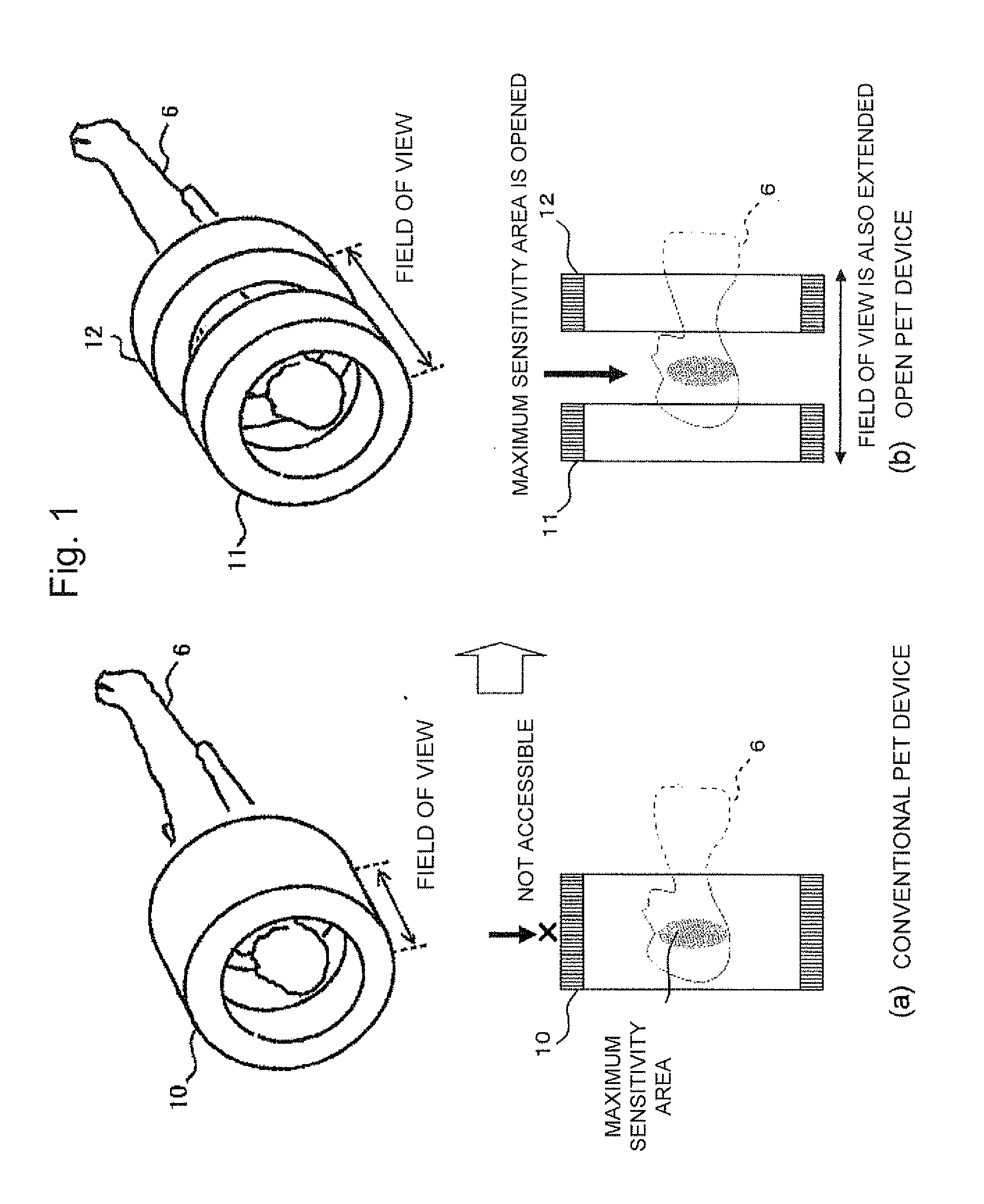
The long tunnel-shaped patient port, however, increases psychological stress on a patient 6 under examination as well as obstructs the patient's treatment.
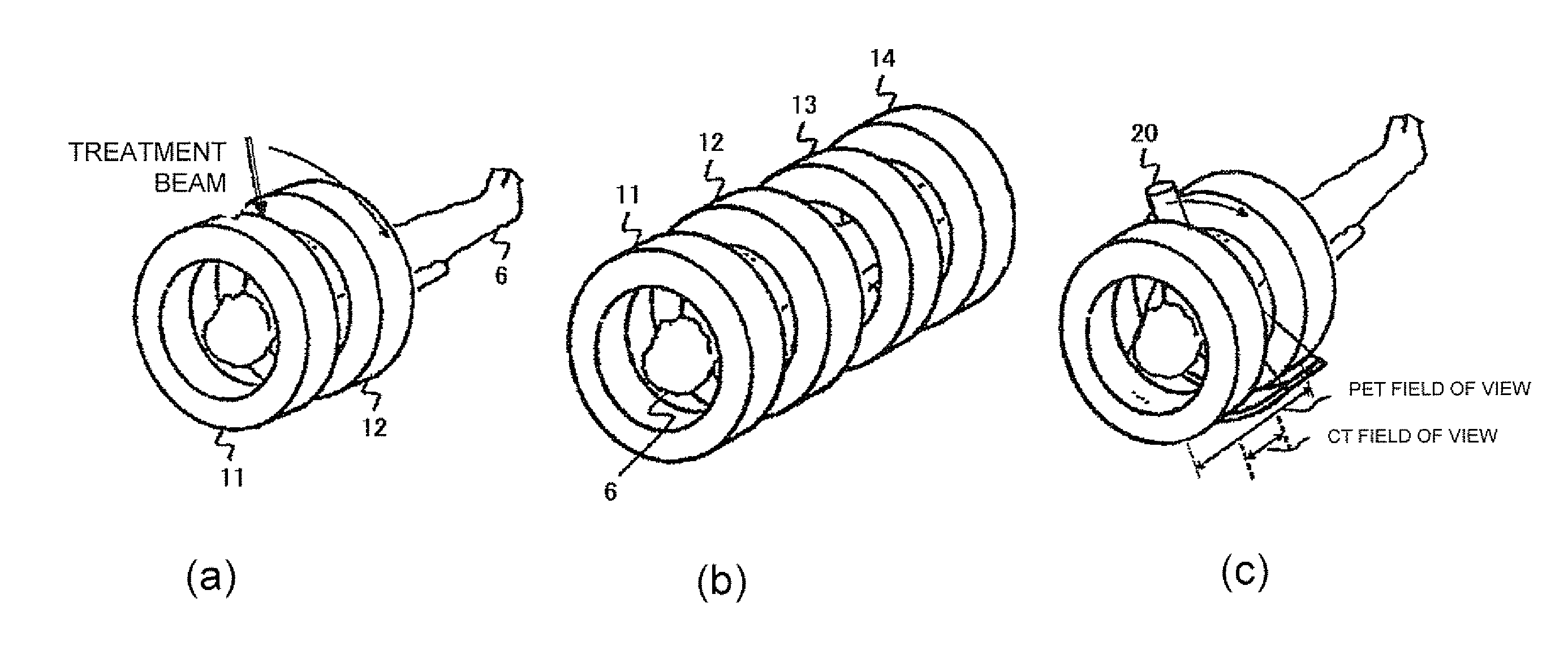
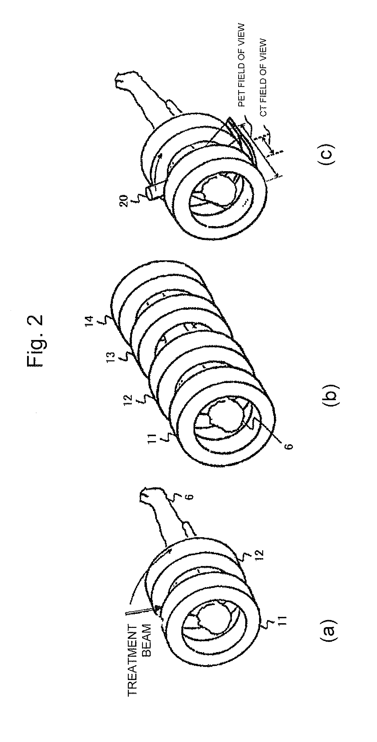
An open PET device enables PET diagnosis during treatment and whole-body simultaneous scanning, which have not been possible with conventional PET devices.
It is therefore possible to build a real-time PET / CT device for simultaneous diagnosis of the same location, which has not been possible with conventional PET / CT devices.
It may be difficult, however, to install various devices at a time since respective PET devices are expensive.
It is therefore desired that device configurations can be changed depending on the type of inspection, whereas complicated changes in device configuration are unfavorable because PET devices and CT devices are heavy in weight and susceptible to vibrations etc.

Method used


Image

  • Multi-purpose pet device
  • Multi-purpose pet device
  • Multi-purpose pet device

Examples


first embodiment

[0046]FIG. 7 shows the configuration of an open PET device, the present invention, which includes two single PET devices. The open PET device includes detector rings 31 and 41, gantry covers 35 and 45 which cover the respective detector rings, and a bed 32 on which a patient 6 lies. The gantries 35 and 45 are equipped with wheels 36 and 46, and have the function of moving back and forth on rails 34 and 44, respectively. In the diagram, 37 designates a patient port.

[0047]Nuclides accumulated in the body of the patient 6 emit a pair of annihilation radiations which travel at angles of approximately 180° from each other in all directions. Single event data SD, which is the measured data on either one of a pair of annihilation radiations, detected by the detector rings 31 and 41 is transmitted to a common coincidence circuit 70. The single event data SD is converted into list mode data LD which is information on a coincidence pair. The list mode data LD is stored into a recording medium...

third embodiment

[0053]FIG. 11 shows the present invention, in which PET is installed more after initial introduction of a PET / CT device. As shown in FIG. 11(a), a PET device 31 and an X-ray CT device 21 are combined to share the patient bed 32. Such a configuration is prevalent for the purpose of superposing CT images having excellent morphological information over PET images to enhance the diagnostic performance of PET for the sake of compensating the drawback of PET images of less anatomical information. FIG. 11(b) shows an example where the detector ring 41 of the additional PET device is arranged on the right of the first detector ring 31 (on the opposite side from the CT device 21) to constitute an OpenPET / CT device. The second detector ring 41 may be configured to be movable on rails 44 in the direction of the body axis, thereby changing the open field of view. As shown to the right of FIG. 11(b), the detector rings 31 and 41 may be connected to constitute a high-sensitivity PET / CT. Alternati...

fourth embodiment

[0054]FIG. 12 shows the present invention, in which (a) two independently operating PET / CT devices 21+31 and 22+41 (conventional PET / CT mode) and (b) a single OpenPET / CT 21+31+41 (OpenPET / CT mode) can be switched. In (b) the OpenPET / CT mode, the remaining second CT device 22 may be used by itself. The second detector ring 41 is mounted on rails 44 that extend in a direction orthogonal to the body axis. To switch from the conventional PET / CT mode to the OpenPET / CT mode, a patient bed 42 is once withdrawn out of the second detector ring 41. The patient bed 32 is further moved to the right in the diagram. The second detector ring 41 is then moved to a position coaxial with the first detector ring 31, and the patient bed 32 is returned to the original position. The first detector ring 31 may be fixed to the floor. The first detector ring 31 may be configured to be movable on the rails 34 in the direction of the body axis so that the open field of view can be changed more freely. Since t...


PUM


Abstract

In an open PET device including a plurality of detector rings that are arranged apart in the direction of the body axis of a subject and having a physical open field of view area, at least one of the detector rings or another imaging device arranged in parallel is configured to be movable by simple device moving means in order to change the configuration of the PET device. This improves the versatility of the open PET device for easier introduction to facilities.

Description

TECHNICAL FIELD[0001]The present invention relates to an open PET device that includes a plurality of separate detector rings arranged apart in the direction of the body axis of a subject and has a physically open field of view area, and more particularly to a multi-purpose PET device that can be easily changed in configuration.BACKGROUND ART[0002]Positron emission tomography (PET) is attracting attention as an effective inspection method for earlier diagnosis of cancer, cerebrovascular disease, dementia, etc. In PET, a compound labeled with a trace amount of positron emitting nuclides is administered and annihilation radiation emitted from inside the body is detected to image metabolic functions such as sugar metabolism and check for a disease and its extent. PET devices for practicing PET have been put into actual use.[0003]To improve the sensitivity of a PET device, as illustrated in FIG. 1(a), a detector 10 needs to be arranged in a tunnel-like configuration for an increased sol...

Claims


Application Information

Patent Timeline
Patent Type & Authority Applications(United States)
IPC IPC(8): G01T1/164
CPCG01T1/1603A61B6/037G01T1/2985
Inventor YAMAYA, TAIGAMURAYAMA, HIDEO
Owner NAT INST FOR QUANTUM & RADIOLOGICAL SCI & TECH
Learn More