Light-emitting device package and method of manufacturing the same

Active Publication Date: 2012-06-28
SAMSUNG ELECTRONICS CO LTD
View PDF1 Cites 12 Cited by
  • Summary
  • Abstract
  • Description
  • Claims
  • Application Information

AI Technical Summary

Benefits of technology

[0007]Provided are light-emitting device packages whi

Problems solved by technology

However, it is difficult to reduce a color variation between signal chip packages in a typical method in which the single chip packages are manufactured and are arrayed.
Thus, a defective proportion may be increased.
In addition, a rigorous production management may be required, process

Method used


Image

  • Light-emitting device package and method of manufacturing the same
  • Light-emitting device package and method of manufacturing the same
  • Light-emitting device package and method of manufacturing the same

Examples


Embodiment Construction

[0030]Various example embodiments will now be described more fully with reference to the accompanying drawings in which example embodiments are shown.

[0031]It will be understood that when an element is referred to as being “connected” or “coupled” to another element, it can be directly connected or coupled to the other element or intervening elements may be present. In contrast, when an element is referred to as being “directly connected” or “directly coupled” to another element, there are no intervening elements present. As used herein the term “and / or” includes any and all combinations of one or more of the associated listed items.

[0032]It will be understood that, although the terms “first”, “second”, etc. may be used herein to describe various elements, components, regions, layers and / or sections, these elements, components, regions, layers and / or sections should not be limited by these terms. These terms are only used to distinguish one element, component, region, layer or secti...


PUM


Abstract

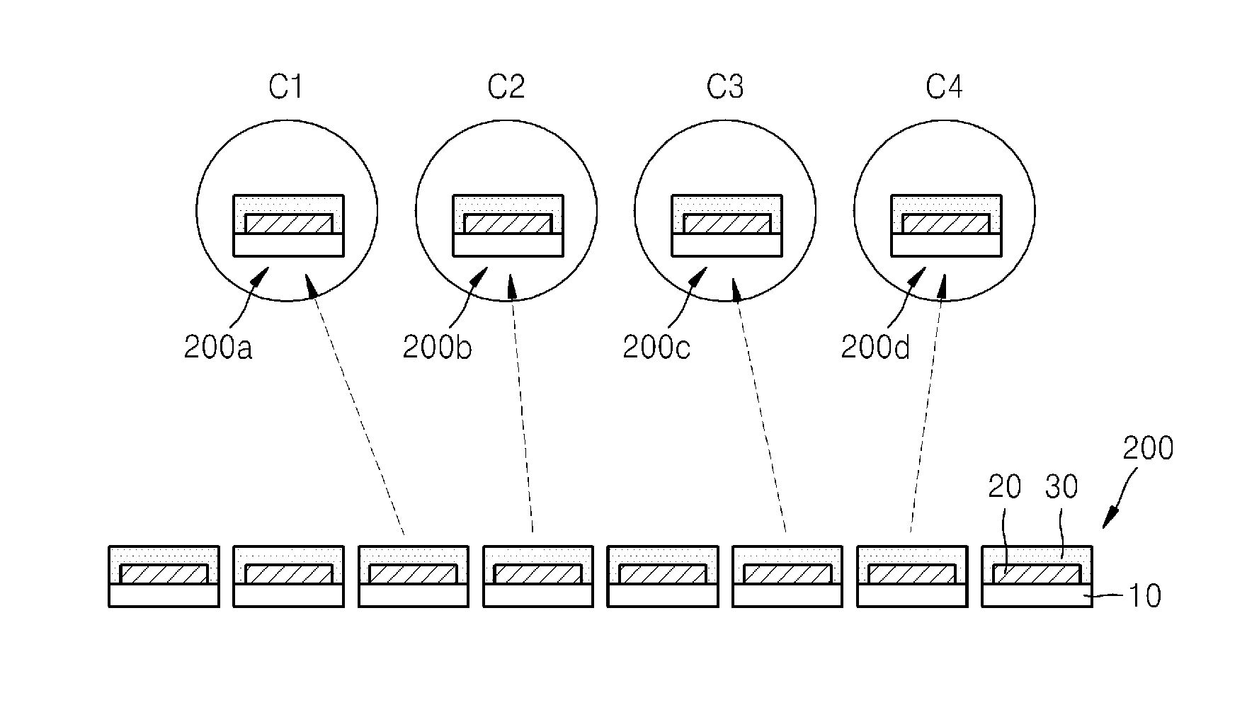
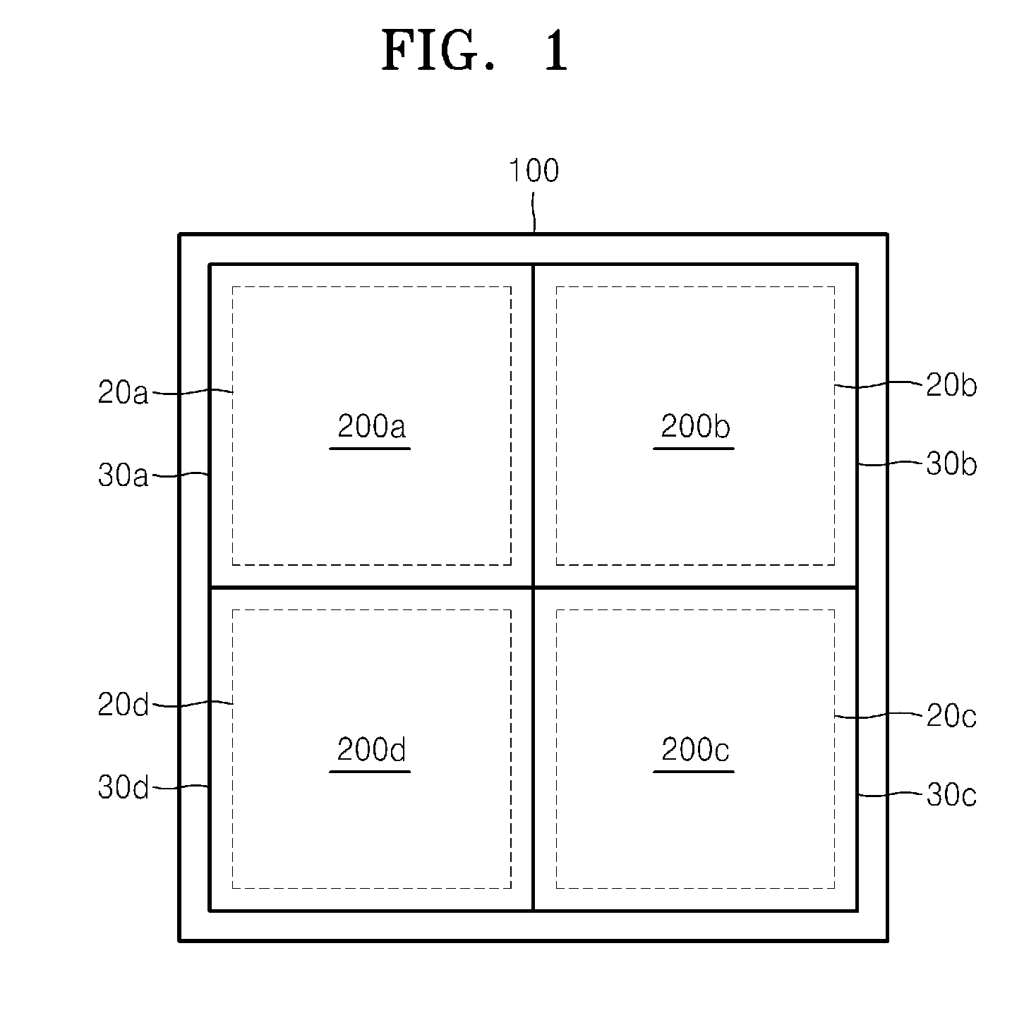
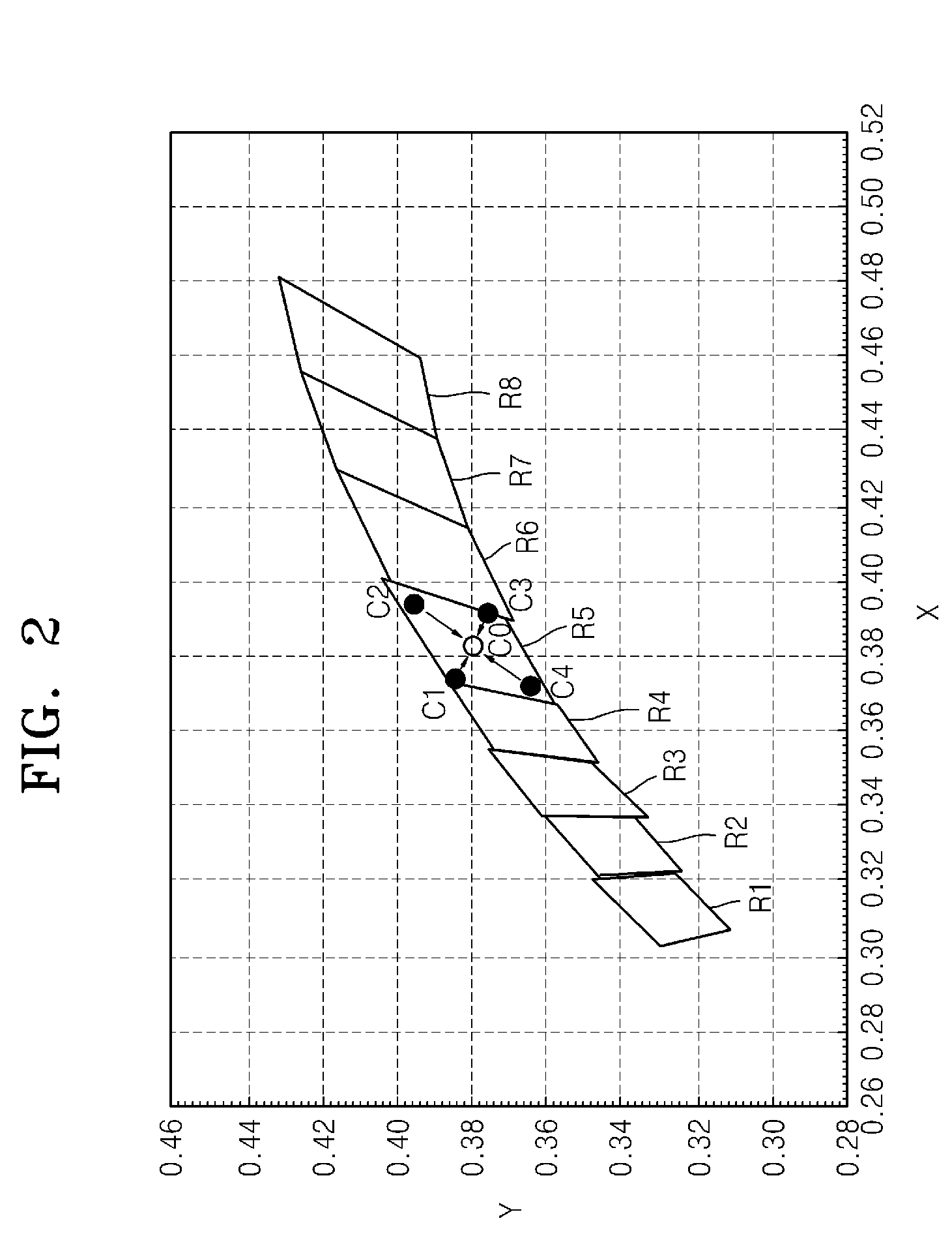
Provided are a light-emitting device package and a method of manufacturing the same. The light-emitting device package may include a plurality of light-emitting chips on one substrate (board). The plurality of light-emitting chips may produce colors around a target color. The target color may be produced by combinations of the colors of light emitted from the plurality of light-emitting chips. The colors around the target color may have the same hue as the target color and have color temperatures different from that of the target color. The plurality of light-emitting chips may have color temperatures within about ±250K of that of the target color.

Description

CROSS-REFERENCE TO RELATED APPLICATIONS[0001]This application claims the benefit of Korean Patent Application No. 10-2010-0134910, filed on Dec. 24, 2010, in the Korean Intellectual Property Office, the disclosure of which is incorporated herein in its entirety by reference.BACKGROUND[0002]1. Field[0003]The present disclosure relates to light-emitting device packages and methods of manufacturing the same.[0004]2. Description of the Related Art[0005]Light-emitting devices such as light emitting diodes (LEDs) and laser diodes (LDs) utilize an electroluminescence phenomenon, that is, a phenomenon in which light is emitted from a material (semiconductor) by applying a current or voltage to the material. Light may be emitted from an active layer (i.e., light-emitting layer) due to combinations of electrons and holes within the active layer, and the light may have energy corresponding to an energy band gap of the active layer.[0006]A light-emitting chip may be mounted on a substrate, and ...

Claims


Application Information

Patent Timeline
IPC IPC(8): H01L33/08H01L33/50
CPCH01L25/0753H01L27/15H01L33/50H01L24/97H01L2924/0002H01L2924/12042H01L2924/00H01L24/95H01L27/156H01L2924/12041
Inventor KIM, HYUNG-KUN
Owner SAMSUNG ELECTRONICS CO LTD
Why Eureka
Try Eureka