Motion image decoding apparatus and method reducing error accumulation and hence image degradation

a motion image and decoding technology, applied in the field of motion image decoding configurations, can solve the problems of increasing the probability of rounding and noticeable degradation, and achieve the effect of reducing error accumulation and reducing noticeable degradation

Inactive Publication Date: 2006-04-04
SANYO ELECTRIC CO LTD
View PDF19 Cites 8 Cited by
  • Summary
  • Abstract
  • Description
  • Claims
  • Application Information

AI Technical Summary

Benefits of technology

[0021]The present invention contemplates a motion image decoding method and

Problems solved by technology

This results in an increased probability of rounding-up in a picture, as seen in its

Method used


Image

  • Motion image decoding apparatus and method reducing error accumulation and hence image degradation
  • Motion image decoding apparatus and method reducing error accumulation and hence image degradation
  • Motion image decoding apparatus and method reducing error accumulation and hence image degradation

Examples


Embodiment Construction

[0034]Configuration of MPEG Decoder 1000

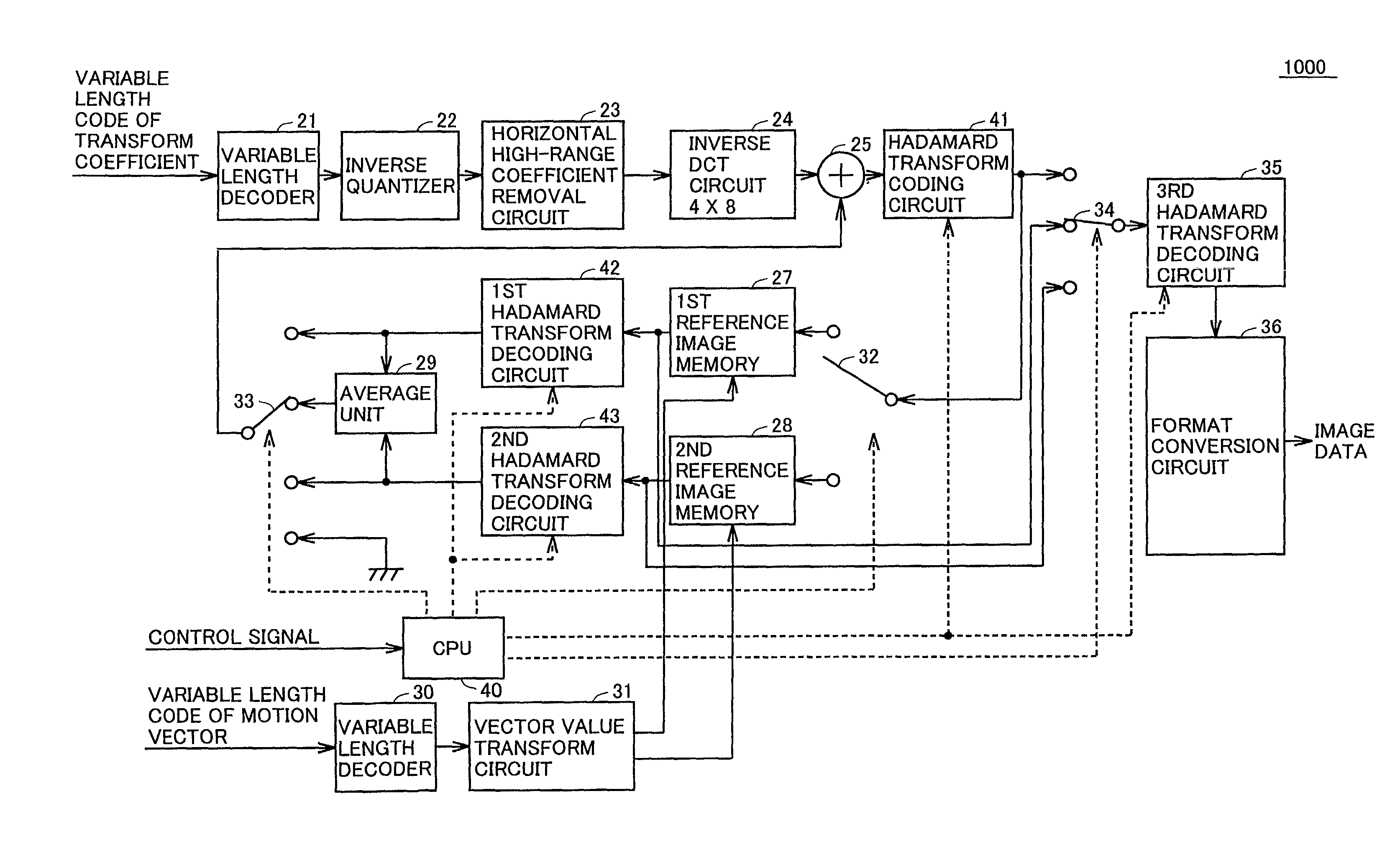
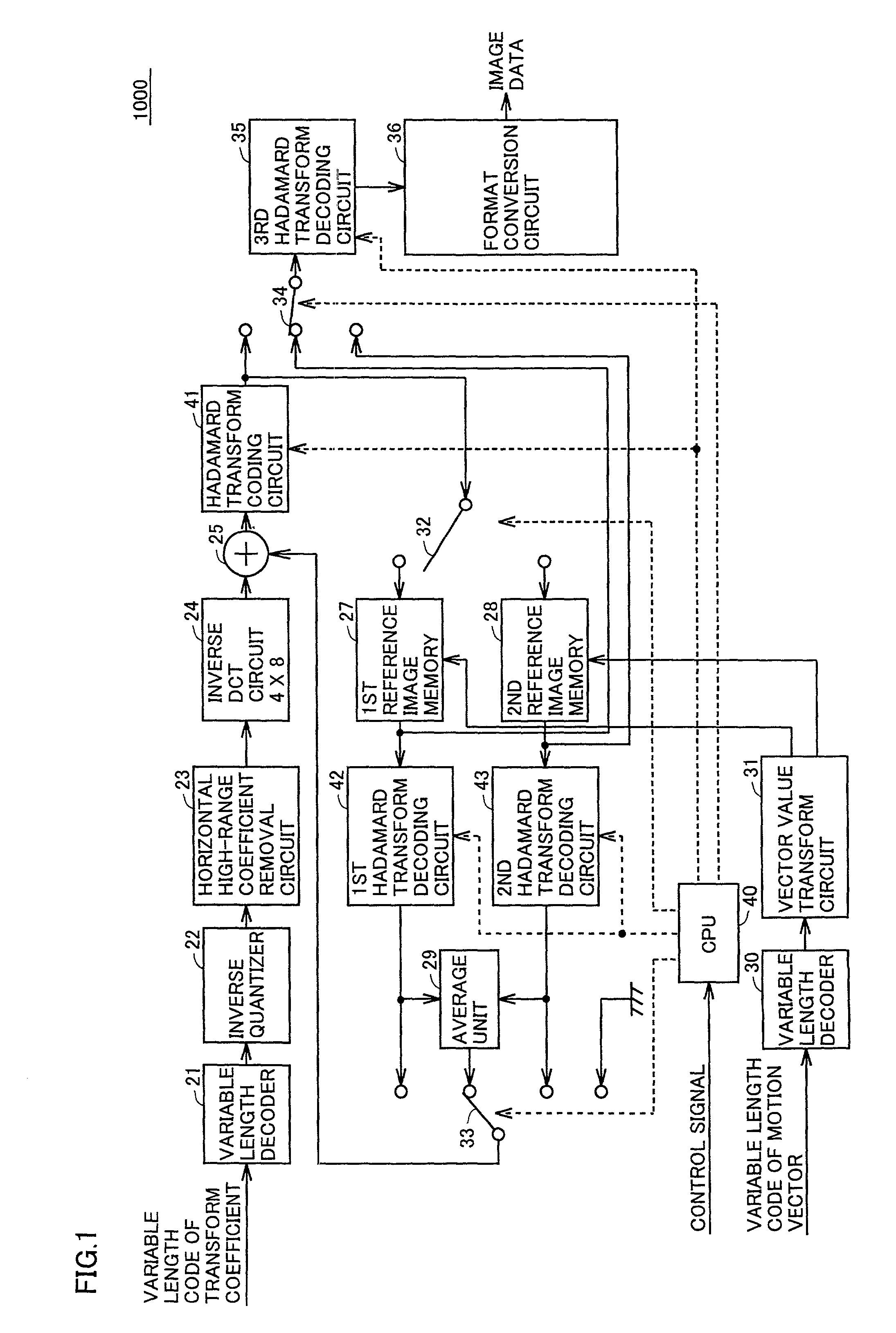
[0035]FIG. 1 is a block diagram schematically showing a configuration of an MPEG decoder 1000.

[0036]As shown in FIG. 1, a variable length code of a transform coefficient is transmitted to a variable length coder 21. A control signal including a block type is transmitted to CPU40. A variable length code of a motion vector is transmitted to and decoded by a variable-length decoder 30. A motion vector obtained in variable length decoder 30 is transmitted to a vector value transform circuit 31 and thus transformed to be horizontally one half in magnitude. The motion vector thus transformed is then transmitted to first and second reference image memories 27 and 28 as a control signal for controlling a position at which a reference image is cut out. A variable length coder 21 decodes a variable length code of a transform coefficient. An inverse quantizer 22 inversely quantizes a transform coefficient obtained from variable length coder 21 (a quantiz...


PUM


Abstract

An Hadamard transform coding circuit changes a rounding method for each Hadamard transform block to prevent a rounding operation from providing an error biased in one direction, as seen in a picture in its entirety, for data compression and rounding. More specifically, after Hadamard transform there exist decimal parts 0.0, 0.25, 0.5 and 0.75, and if a numerical value is simply rounded off a probability would be increased that the numerical value is biased to increase in absolute value. Accordingly for 0.5 a rounding operation to provide an integer switches for each block. Thus a motion image decoding apparatus can be provided to reduce error accumulation and suppress flickering, color variation and other similar noticeable degradations.

Description

BACKGROUND OF THE INVENTION[0001]1. Field of the Invention[0002]The present invention relates to configurations of motion image decoding methods and apparatuses decoding a signal coded and compressed in a system such as the Moving Picture Experts Group (MPEG) compression.[0003]2. Description of the Background Art[0004]In a field for example of digital TVs, MPEG systems are known as an image coding system used to code and compress image data.[0005]The MPEG systems are represented by MPEG-1 and MPEG-2. MPEG-1 is only intended for non-interlaced images, whereas MPEG-2 is intended not only for non-interlaced images but also interlaced images.[0006]Such MPEG coding adopts motion compensation prediction (temporal compression), discrete cosine transform (DCT) (spatial compression), and entropy coding (variable-length coding). In the MPEG coding, timebase predictive coding is initially effected for each macroblock serving as a unit, hereinafter referred to as a “unit macroblock.” In MPEG-1 ...

Claims


Application Information

Patent Timeline
IPC IPC(8): G06K9/36H04N11/04H03M7/30H03M7/40H04N19/423H04N19/44H04N19/48H04N19/50H04N19/503H04N19/51H04N19/60H04N19/61H04N19/625H04N19/85H04N19/91
CPCH04N19/60
Inventor HIRASE, KATSUNORI
Owner SANYO ELECTRIC CO LTD
Why Eureka
Try Eureka