Current regulating circuit of light emitting diode (LED) string and LED illumination device

a technology of led string and current regulating circuit, which is applied in the direction of electroluminescent light source, semiconductor lamp usage, electrical lighting source, etc., can solve the problems of difficulty in evenly distributing input current from power converter to led string, and unsatisfactory uniformity of led output brightness. achieve the effect of reducing power consumption and facilitating energy to be recycled

Active Publication Date: 2012-06-28
AU OPTRONICS CORP
View PDF3 Cites 5 Cited by
  • Summary
  • Abstract
  • Description
  • Claims
  • Application Information

AI Technical Summary

Benefits of technology

[0012]In the above exemplary embodiments, owing to the novel design of current regulating circuit of light emitting diode string, in which the terminal voltage of LED string is detected and controlled to thereby allow the currents flowing through the respective light emitting diode strings to be prone to the same, so that the phenomenon of unevenly distribution of input current can be effectively improved and therefore the issue of uneven light emitting diode brightness can be solved consequently. In addition, the use of energy storage and release characteristics of capacitor and inductor cooperative with the control of switch facilitates the energy to be recycled in use, the issue of large power consumption caused by the conventional current adjustment circuit generally operated in resistive state can be overcome, so that the currents flowing through the respective light emitting diode strings are uniform / stabilized and the power consumption is reduced.

Problems solved by technology

However, since the LED strings actually have some differences thereamong, currents flowing through the respective LED strings are not completely the same, so that the uniformity of the LED output brightnesses is unsatisfactory.
However, since the turned on switches S1, S2, S3 are resistive states, resistance differences among the LED strings still are not satisfactorily compensated, so that the LED strings are operated with unbalanced currents, an input current from the power converter is difficult to be evenly distributed to the LED strings and therefore the uniformity of the LED output brightnesses still is unsatisfactory.

Method used


Image

  • Current regulating circuit of light emitting diode (LED) string and LED illumination device
  • Current regulating circuit of light emitting diode (LED) string and LED illumination device
  • Current regulating circuit of light emitting diode (LED) string and LED illumination device

Examples


Embodiment Construction

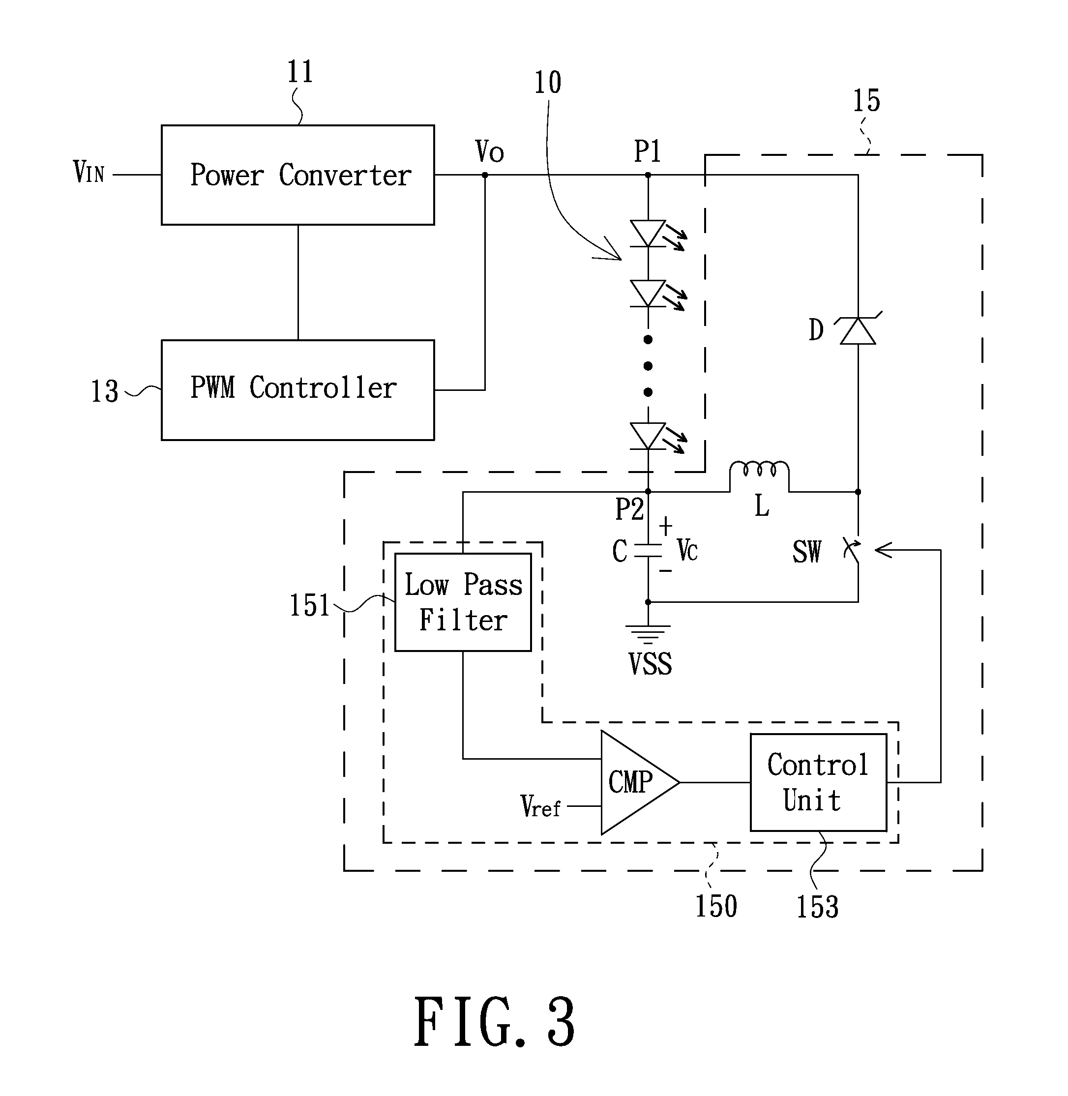
[0019]The disclosure will now be described more specifically with reference to the following embodiments. It is to be noted that the following descriptions of embodiments are presented herein for purpose of illustration and description only. It is not intended to be exhaustive or to be limited to the precise form disclosed.

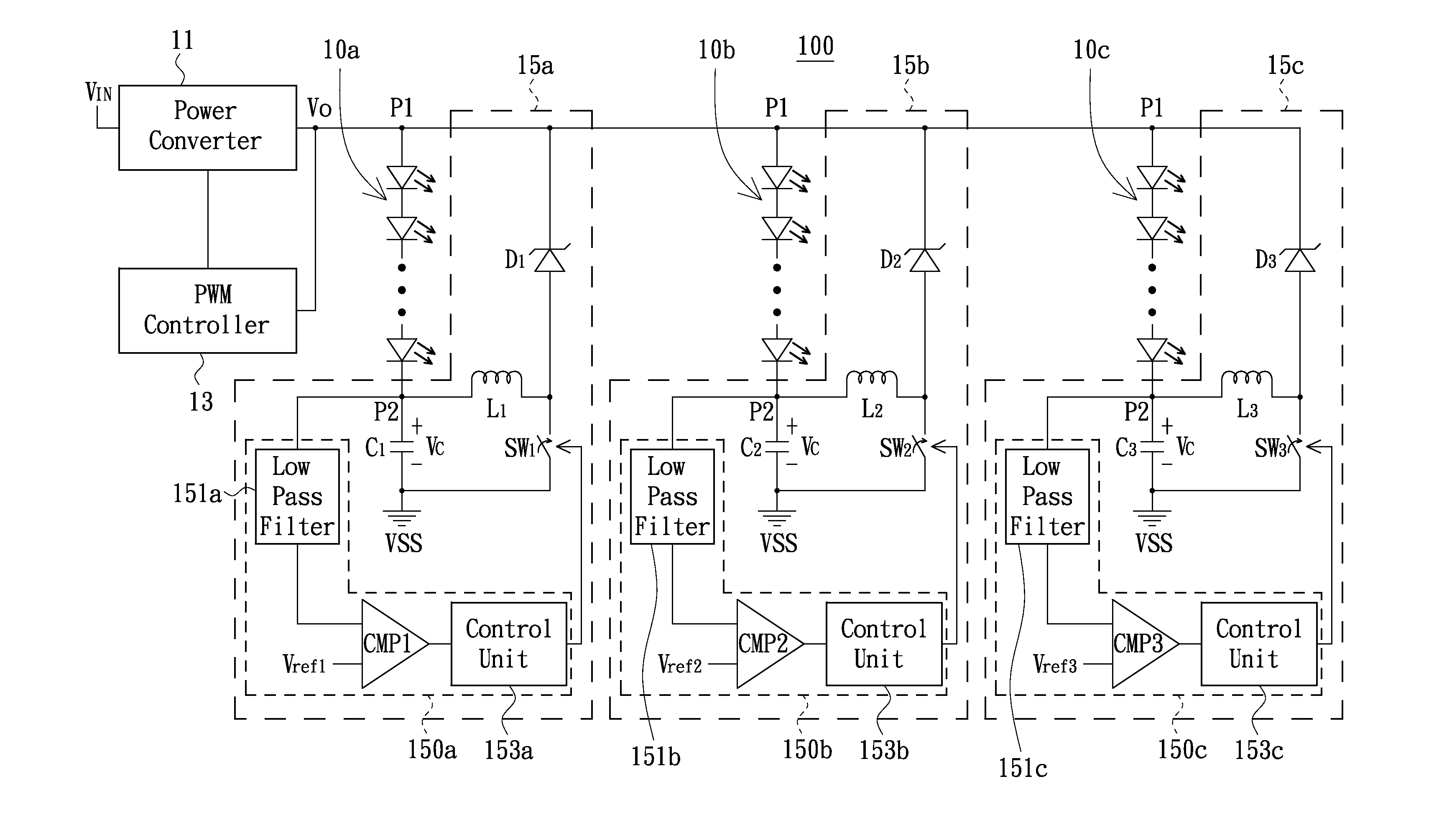
[0020]Referring to FIG. 3, a schematic circuit structure of a light emitting diode circuit with a current regulating circuit of light emitting diode string in accordance with an embodiment is shown. As depicted in FIG. 3, the light emitting diode string 10 is electrically coupled between a high voltage terminal P1 and a low voltage terminal P2 to receive a high voltage and a low voltage. The power converter 11 receives an input voltage VIN and thereby outputs an output voltage Vo to the high voltage terminal P1 of the light emitting diode string 10 after voltage conversion. The pulse width modulation (PWM) controller 13 is electrically coupled to the high voltage ...


PUM


Abstract

An exemplary current regulating circuit of LED string includes a capacitor, an inductor, a diode, a switch and a detection circuit. First and second terminals of the capacitor respectively are connected to a low voltage and a preset voltage. A first terminal of the inductor is connected to the low voltage. Positive and negative terminals of the diode are respectively connected to a second terminal of the inductor and a high voltage. First and second terminals of the switch are respectively connected to the second terminal of the inductor and the preset voltage. The detection circuit detects the low voltage to thereby switch ON-OFF states of the switch in demand. Moreover, a LED illumination device using the current regulating circuit also is provided.

Description

1. TECHNICAL FIELD[0001]The disclosure relates to light emitting diode (LED) control technologies, and more particularly to a current regulating circuit of LED string(s) and a LED illumination device.2. DESCRIPTION OF THE DISCLOSURE[0002]The light emitting diode is a type of P-N diode manufactured by special materials, and when the LED is forward-biased, electrons would be recombined at the p-n junction interface to thereby emit light, which is one type of electroluminescent effects. The LED would emit lights with different wavelengths induced by different metal element additions and different ratios of chemical components in the manufacturing process of LED wafer. Early light emitting diodes only can emit blue, green, yellow and red colors of lights, and are primarily applied to indicator lights and display boards. With the emergence of white LEDs, LEDs are further applied for illumination. It is well known that, the LEDs have the advantages of high-efficiency energy conversion, fa...

Claims


Application Information

Patent Timeline
Patent Type & Authority Applications(United States)
IPC IPC(8): H05B37/02H05B44/00
CPCH05B33/0815H05B33/0827Y02B20/347Y02B20/346H05B33/0848H05B45/14H05B45/46Y02B20/30H05B45/3725
Inventor LIN, HUANG-TICHANG, WEN-TICHANG, CHIA-YUANHUANG, CHUN-CHIEH
Owner AU OPTRONICS CORP
Why Eureka
Try Eureka