Mount structure of touch panel with vibration function

Active Publication Date: 2012-06-28
NISSHA PRINTING COMPANY
View PDF26 Cites 107 Cited by
  • Summary
  • Abstract
  • Description
  • Claims
  • Application Information

AI Technical Summary

Benefits of technology

[0038]According to the present invention, the touch panel with the vibration function has the design sheet having the transparent window part and the decorative part surrounding that transparent window part on the upper surface of the touch panel body, and this is externally fitted in the casing, so that a seamless structure is provided such that there is no seam between an external surface of the touch panel with the vibration function and an external surface of the casing. In addition, the elastic member frame is arranged on the support part of the casing so as to be positioned on the outer edge side of the touch panel body with respect to the vibrato

Problems solved by technology

(1) According to the resistive type touch panel, as described above, since the movable plate and the support substrate have the laminated structure in which they are arranged with the slight insulation space left between them, pressed stroke to the movable plate is extremely small such as 0.01 to 0.5 mm, so that it is difficult for the operator to feel input operational feeling.
In addition, as for the capacitive type, since the pressed stroke does not exist, the operator cannot feel the input operational feeling.

Method used


Image

  • Mount structure of touch panel with vibration function
  • Mount structure of touch panel with vibration function
  • Mount structure of touch panel with vibration function

Examples


first embodiment

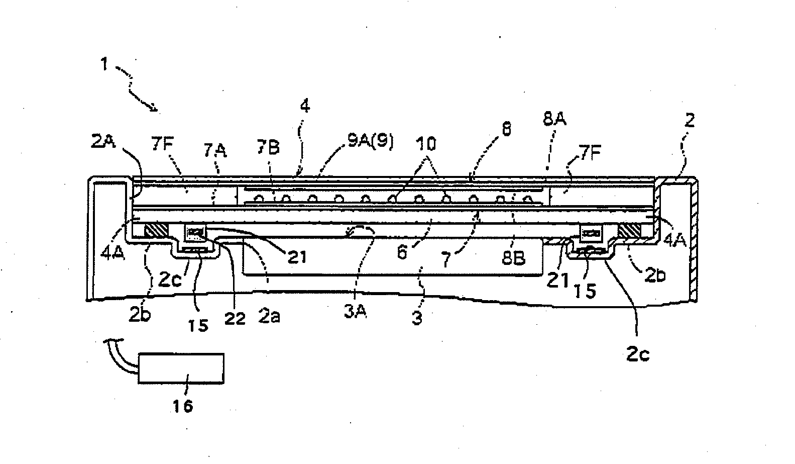
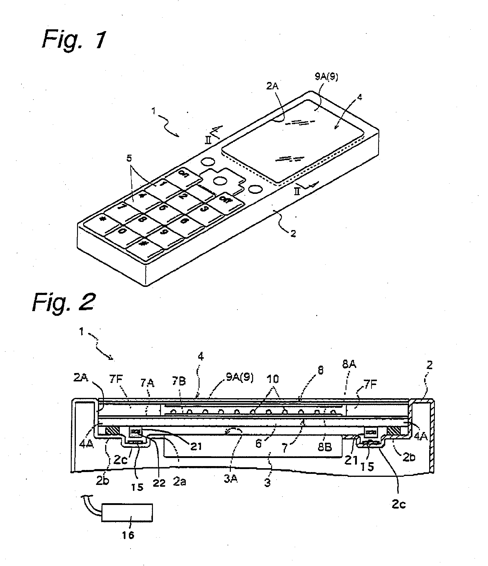
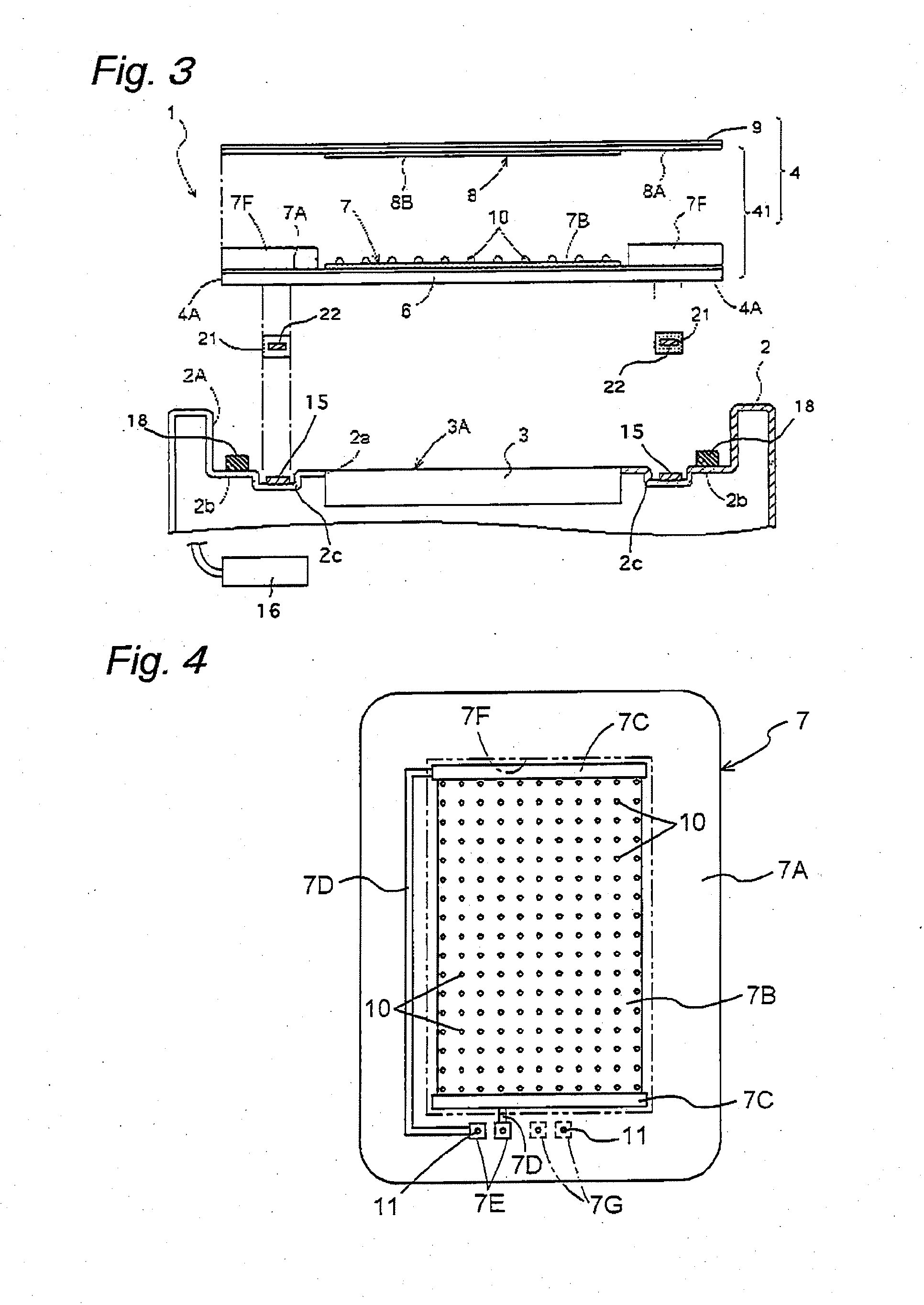
[0058]A panel member according to the present invention is used for mobile devices such as a portable telephone, smart phone, PDA, car navigation device, digital camera, digital video camera, and portable game machine. Here, a description will be made by illustrating a mount structure of a tactile feedback type touch panel used for the portable telephone as a panel member. FIG. 1 is a perspective view of a portable telephone 1. FIG. 2 is a cross-sectional view showing one example of a mount structure of a touch panel with a vibration function taken along a line II-II in FIG. 1, and FIG. 3 is an exploded cross-sectional view showing the one example of the mount structure of the touch panel with the vibration function.

[0059]As shown in FIGS. 1 to 3, the portable telephone 1 having a touch panel 4 with a vibration function includes a synthetic resin casing 2 having a display window 2A etc. in its front surface, a display device 3 having a display part 3A such as a liquid crystal or an ...

second embodiment

[0104]Next, a description will be made by illustrating an example of a mount structure serving both as a touch panel and a speaker used in a portable telephone, as a panel member according to the present invention. FIG. 14 is a cross-sectional view showing an other example of a mount structure of a touch panel with a vibration function taken along a line II-II in FIG. 1, and FIG. 15 is an exploded cross-sectional view showing the other example of the mount structure of the touch panel with the vibration function.

[0105]While the tactile feedback control unit 16 is arranged inside the casing 2 as the vibration control unit in the first embodiment, a second embodiment only differs from the first embodiment in that a speaker control unit 17 is arranged inside the casing 2 as a vibration control unit (refer to FIGS. 14 and 15), and others are the same as those of the first embodiment. The speaker control unit 17 applies a predetermined drive voltage to the piezoelectric element 22 servin...


PUM


Abstract

[Object] It is an object to provide a mount structure of a touch panel with a vibration function which is superior in impact resistance, dust-proofness, and drip-proofness, and can effectively transmit a vibration of a vibration element.
[Solution to Problem] The mount structure of the touch panel with the vibration function is characterized by including a touch panel body, a design sheet bonded to an upper surface of the touch panel body and having a transparent window part and a decorative part surrounding the transparent window part, a vibration element formed in a back surface peripheral part of the touch panel body and hidden by the decorative part, a casing dented so as to have a level difference to allow the above parts to be externally fitted in and having a recess part or an opening part for a display device, and a frame-shaped support part to support the back surface peripheral part of the touch panel body, in its bottom surface, an elastic member frame arranged on the support part and positioned on an outer edge side of the touch panel with respect to the vibrator, and a vibration control unit arranged inside the casing to apply a drive voltage to the vibration element.

Description

TECHNICAL FIELD[0001]The present invention relates to a mount structure of a touch panel with a vibration function mainly used for a mobile device such as a portable telephone, smart phone, PDA, car navigation device, digital camera, digital video camera, and portable game machine.BACKGROUND ART[0002]While a mobile device having a touch panel mounted on a front surface of a display device is in the wide market at the present, the touch panel mainly comes in a resistive type touch panel and a capacitive type touch panel. According to the resistive type touch panel, a movable plate and a support substrate are laminated with a slight insulation space left between the movable plate and the support substrate such that conductor layers formed on their opposed surfaces are separated from each other, and when the movable plate is pressed, the fact that the conductor layers are brought into contact with each other at the pressed position is electrically detected, and pressed position data re...

Claims


Application Information

Patent Timeline
IPC IPC(8): G06F3/043
CPCG06F1/1626G06F3/016G06F3/041H04M1/0266H04M1/0283H04R2499/11H04M19/047H04M2250/22H04R17/00H04R2400/03H04M1/03G06F3/045
Inventor KAI, YOSHIHIROHASHIMOTO, TAKAOSUETOMI, YOSHIKOWATAZU, YUJI
Owner NISSHA PRINTING COMPANY
Why Eureka
Try Eureka