
Display driver circuit, liquid crystal display device, display driving method, control program, and computer-readable recording medium having same control program recorded therein

a display driver and liquid crystal display technology, applied in the direction of instruments, computing, conversion involving interpolation processes, etc., can solve the problems of flicker, reduced luminance level, and observed motion blur by viewers, and achieve the effect of improving the characteristic of moving image respons

Inactive Publication Date: 2012-06-28
SHARP KK
View PDF15 Cites 10 Cited by
  • Summary
  • Abstract
  • Description
  • Claims
  • Application Information

AI Technical Summary

Benefits of technology

The present invention relates to a technique for reducing motion blur in hold-type display devices such as liquid crystal display devices. The technique involves inserting interpolation frames between frames of the display to smoothly move objects in the display. However, when the frame interpolation technique is combined with overshooting, there is a problem of decreased response speed in a region of an intermediate gradation. The invention proposes a solution to this problem by providing a method for generating interpolation frames with an intermediate gradation in response to motion vectors and video signals. This method allows for a smoother motion of objects in the display and reduces motion blur without causing flicker.

Problems solved by technology

Hold-type display devices such as liquid crystal display devices have a problem that, in a case where a moving image is displayed, a blurred image (so-called motion blur) is observed by a viewer since there occurs a gap between a point of viewer's gaze following an object and a position of the object that is being displayed.
However, this method has a problem that flicker is likely to occur since bright and dark states are repeated on an entire screen in each frame.
Moreover, there is a problem that, in a case where a luminance level of a video signal is maximum (e.g., white display of 100% luminance level), providing a display period of a minimum luminance level within 1 frame period causes a reduction in luminance level.

Method used


Image

  • Display driver circuit, liquid crystal display device, display driving method, control program, and computer-readable recording medium having same control program recorded therein
  • Display driver circuit, liquid crystal display device, display driving method, control program, and computer-readable recording medium having same control program recorded therein
  • Display driver circuit, liquid crystal display device, display driving method, control program, and computer-readable recording medium having same control program recorded therein

Examples


embodiment 1

[0071]Embodiment 1 of the present invention is described below with reference to the drawings.

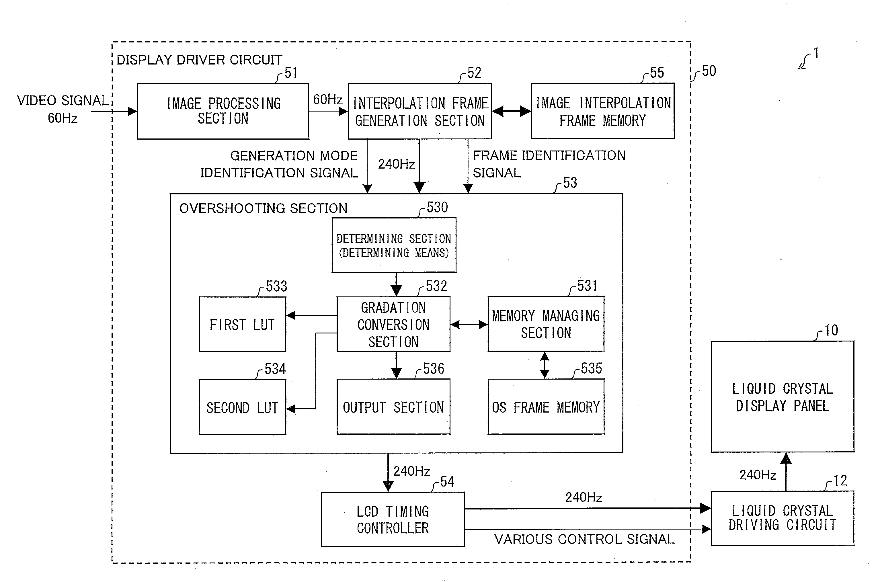
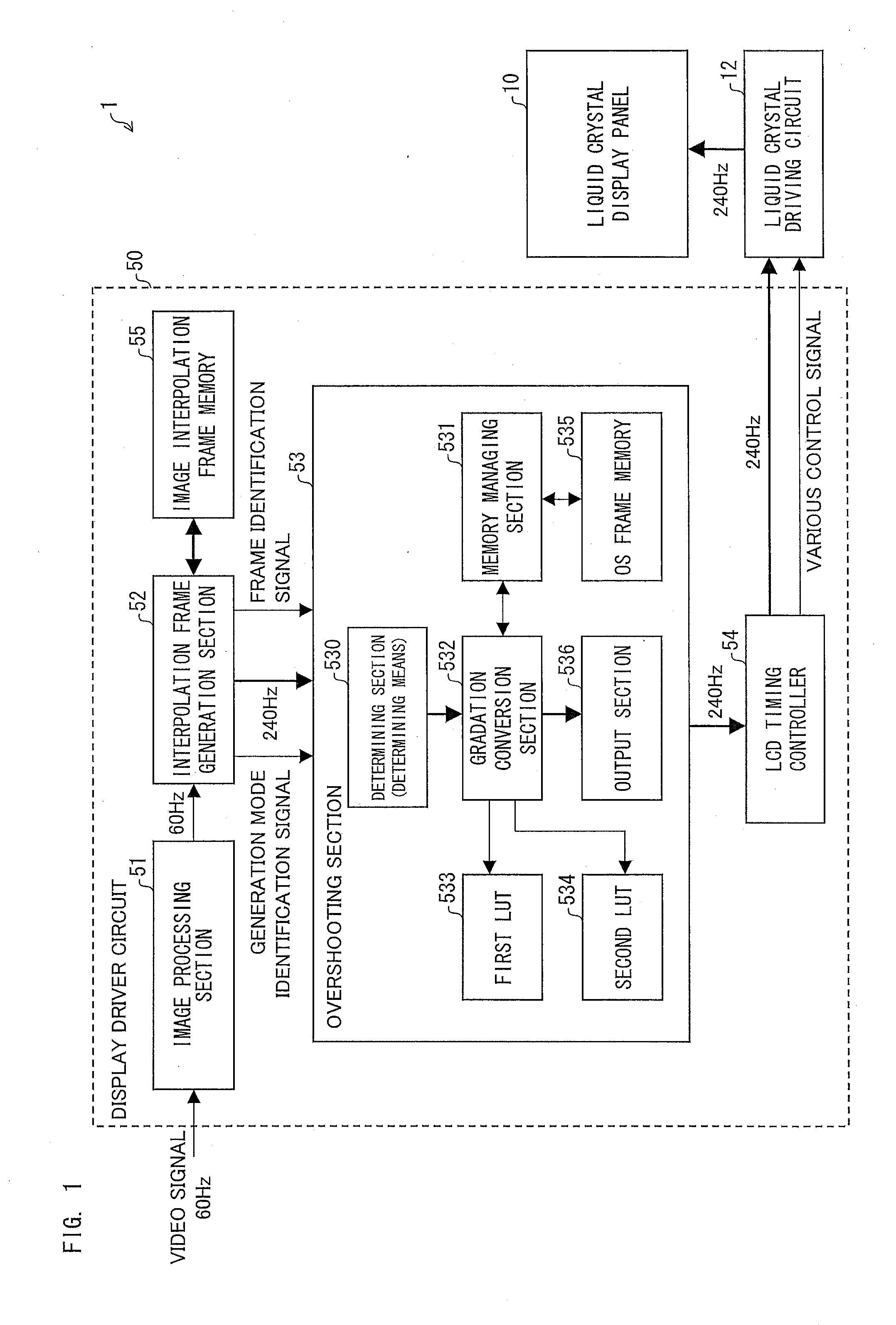
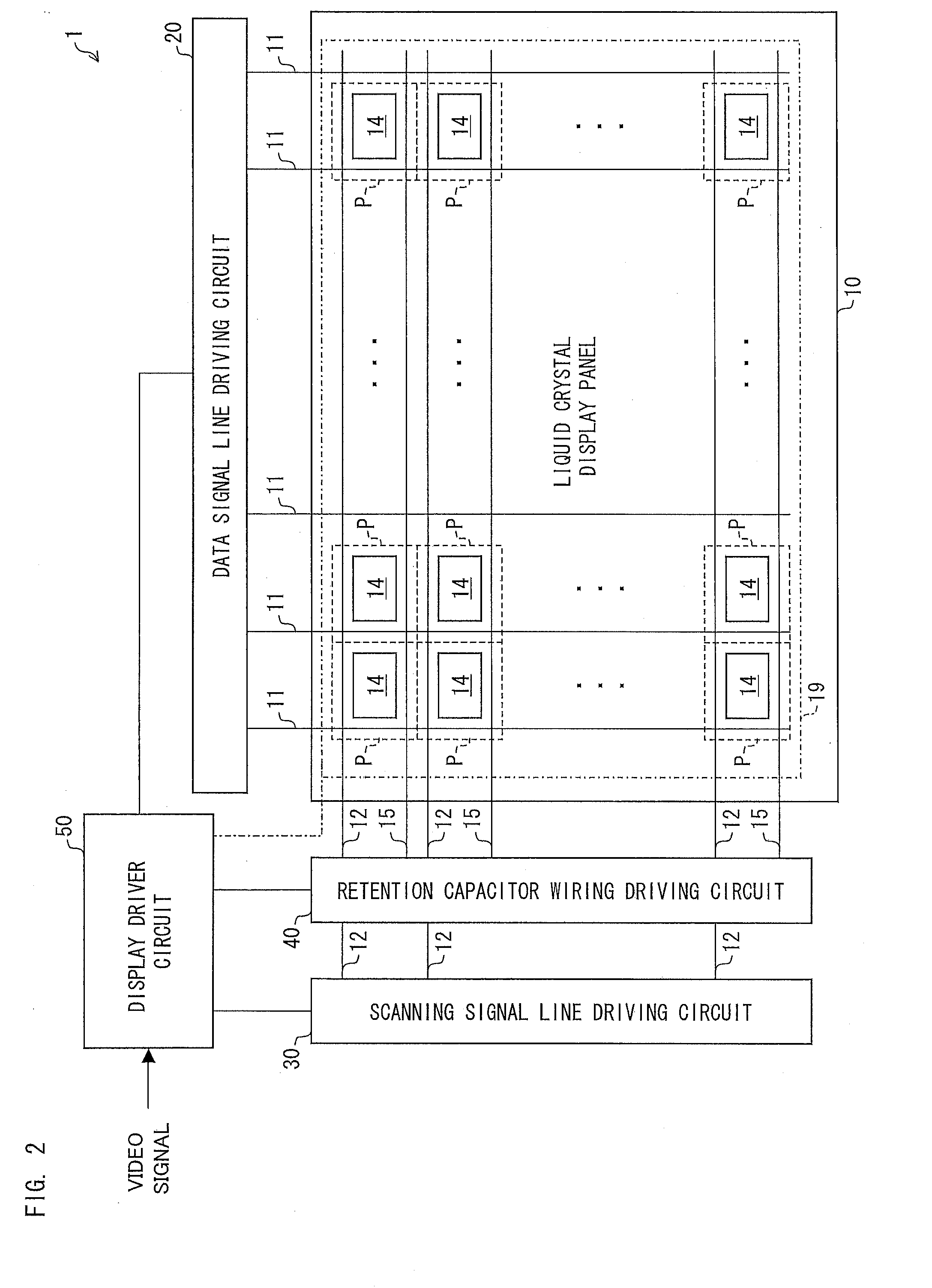
[0072]First, a configuration of a liquid crystal display device 1 of the present invention is described with reference to FIGS. 1 through 3. FIG. 1 is a block diagram illustrating an overall configuration of the liquid crystal display device 1. FIG. 2 is a diagram illustrating an outline configuration of a liquid crystal display panel 10. FIG. 3 is an equivalent circuit diagram illustrating an electrical configuration of each pixel of the liquid crystal display panel 10.

[0073]The liquid crystal display device 1 includes the liquid crystal display panel 10; and a data signal line driving circuit (source driver) 20, a scanning signal line driving circuit (gate driver) 30, and a retention capacitor wiring driving circuit (CS driver) 40 which constitute a liquid crystal driving circuit; and a display driver circuit 50.

[0074]The liquid crystal display panel 10 includes an active matrix substrate...

embodiment 2

[0146]Embodiment 2 of the present invention is described below with reference to the drawings. For convenience of description, members that have identical functions to those in Embodiment 1 are given identical reference numerals, and are not explained repeatedly. Further, the terms defined in Embodiment 1 are used according to the same definition also in the present embodiment unless otherwise specified.

[0147]FIG. 11 is a block diagram illustrating an overall configuration of a liquid crystal display device 2 of the present Embodiment 2. The liquid crystal display device 2 of the present Embodiment 2 is different from the liquid crystal display device 1 of Embodiment 1 in that the interpolation frame generation section 52 does not output the generation mode identification signal. Accordingly, in the present liquid crystal display device 2, overshooting is carried out according to the strong setting with respect to an interpolation frame regardless of whether the interpolation frame ...


PUM


Abstract

Provided is a display driver circuit which carries out frame interpolation and overshooting. An interpolation frame generation section has (i) a first generation mode of generating, based on an image of a key frame corresponding to a video signal, an interpolation frame so that a position of an object is changed with passage of time and (ii) a second generation mode of generating, based on the image of the key frame, an interpolation frame so that a display gradation of the object is changed with passage of time. An overshooting section causes an emphasis level in a tone transition for the interpolation frame generated according to the second generation mode to be different from that for the key frame. Thus, a configuration is proposed which can improve a moving image response characteristic in a display driver circuit which carries out frame interpolation and overshooting.

Description

TECHNICAL FIELD[0001]The present invention relates to a hold-type display device such as a liquid crystal display device.BACKGROUND ART[0002]Hold-type display devices such as liquid crystal display devices have a problem that, in a case where a moving image is displayed, a blurred image (so-called motion blur) is observed by a viewer since there occurs a gap between a point of viewer's gaze following an object and a position of the object that is being displayed.[0003]One example of a method for solving the motion blur problem is a method of providing a display period of a minimum luminance level (e.g., black display of 0% luminance level) in a part of 1 frame period.[0004]However, this method has a problem that flicker is likely to occur since bright and dark states are repeated on an entire screen in each frame. Moreover, there is a problem that, in a case where a luminance level of a video signal is maximum (e.g., white display of 100% luminance level), providing a display period...

Claims


Application Information

Patent Timeline
Patent Type & Authority Applications(United States)
IPC IPC(8): G09G3/36G09G5/10G09G5/00
CPCG09G3/3685G09G2300/0814G09G2300/0876G09G2320/0252G09G2300/0426G09G2340/0435G09G2340/16H04N7/0132H04N7/014G09G2320/0261
Inventor SHIOMI, MAKOTO
Owner SHARP KK
Learn More