Apparatus and method for measuring transmittance

a transmittance and apparatus technology, applied in the direction of transmissivity measurement, material analysis through optical means, instruments, etc., can solve the problems of lack of stability of the output of light sources, lack of accuracy, cost and maintenance, and current transmittance monitoring technologies that require improvement, etc., to achieve the effect of monitoring light transmittan

Inactive Publication Date: 2012-06-28
002134761 ONTARIO
View PDF1 Cites 12 Cited by
  • Summary
  • Abstract
  • Description
  • Claims
  • Application Information

AI Technical Summary

Benefits of technology

[0007]The present invention provides a device that monitors light transmittance using an inexpensive light source and power supply by compensating for light source drift and fluctuations using only one light sensor and one light beam without an expensive optical system, without practical limitations on path-length, and without the errors caused by using reference wavelengths.

Problems solved by technology

However, current transmittance monitoring technologies require improvement.
One of the main issues affecting the accuracy, cost and maintenance of current transmittance monitoring devices is a lack of stability of the output of the light sources.
This lack of stability manifests as sudden output fluctuations over the short term, medium term drift due to temperature and humidity effects on the lamp and power supply electronics, and long term drift due to aging of the light source.

Method used


Image

  • Apparatus and method for measuring transmittance
  • Apparatus and method for measuring transmittance
  • Apparatus and method for measuring transmittance

Examples


Embodiment Construction

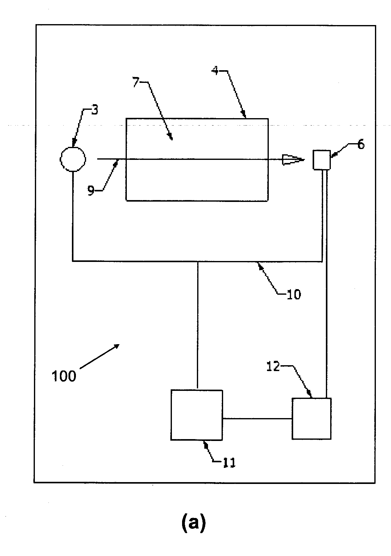
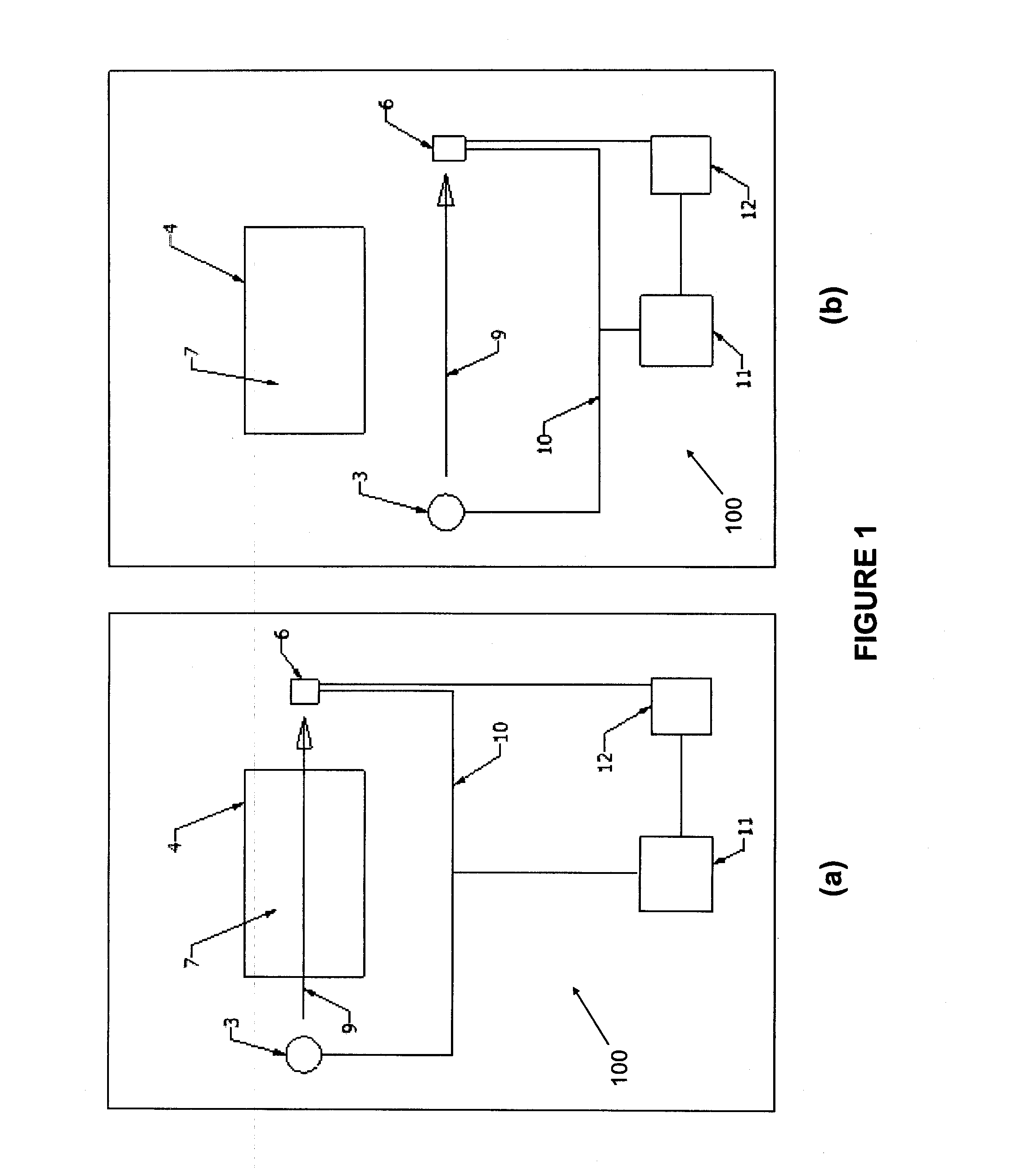
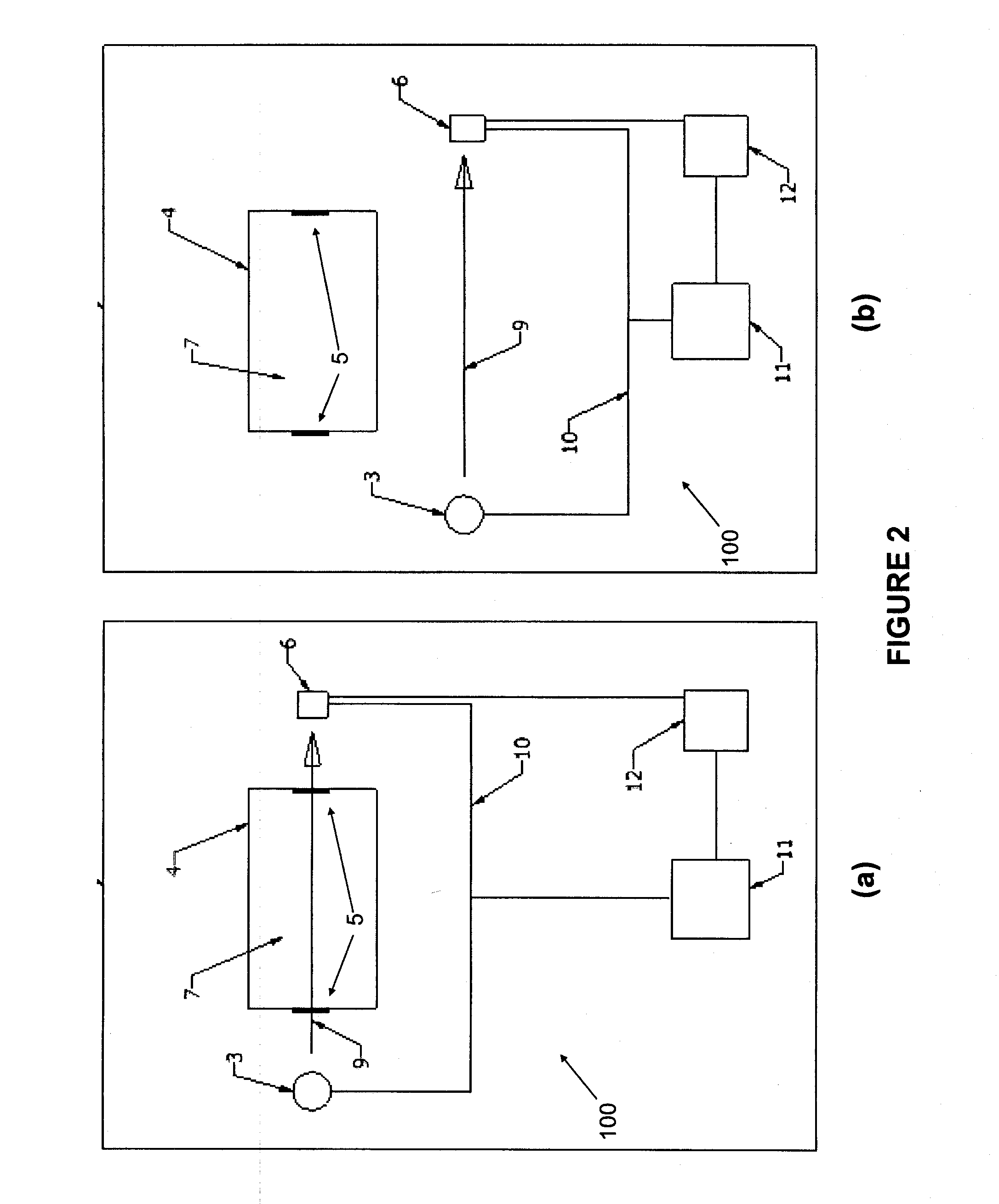
[0024]Without limitation, the majority of the systems described herein are directed to an apparatus and method of measuring optical properties of water. As required, embodiments of the present invention are disclosed herein. However, the disclosed embodiments are merely exemplary, and it should be understood that the invention may be embodied in many various and alternative forms.

[0025]The figures are not to scale and some features may be exaggerated or minimized to show details of particular elements while related elements may have been eliminated to prevent obscuring novel aspects. Therefore, specific structural and functional details disclosed herein are not to be interpreted as limiting but merely as a basis for the claims and as a representative basis for teaching one skilled in the art to variously employ the present invention. For purposes of teaching and not limitation, the illustrated embodiments are directed to real-time industrial and municipal water and liquid quality mo...


PUM

PropertyMeasurementUnit
distanceaaaaaaaaaa
distanceaaaaaaaaaa
transmittanceaaaaaaaaaa

Abstract

A device to measure the amount of light able to transmit through a liquid. The device uses a light detector and light source mounted to a support mechanism such that the detector and light source define a path of light emitted by the light source and detected by the detector. The device uses a structure designed to surround a liquid to be tested such that the structure allows light to transmit through the structure and the liquid. An actuator engenders relative motion between the support mechanism and the structure such that at certain times the light propagating between the light source and the detector passes substantially through the structure and the liquid to be tested such that the amount of light able to transmit through the liquid is detected by the detector, and at other times the light propagates directly from the light source to the detector without passing through the structure or the liquid such that the amount of light emitted from the light source is directly detected by the detector. A microprocessor then uses the two sets of detector readings to allow the transmittance measurement of the liquid to be compensated for errors introduced by drift and fluctuations in the amount of light emitted by the light source and also by drift in the light detector and electronics. Such fluctuation and drift is very common in light sources and is due primarily to changes in temperature and imperfections in the light source itself and the power supply.

Description

FIELD OF THE INVENTION[0001]The present invention is related to real-time industrial and municipal water and liquid quality monitoring. This type of device is used in a variety of applications such as monitoring quality of plant effluent, industrial process control, and security monitoring of drinking water distribution systems.BACKGROUND OF THE INVENTION[0002]Recently, industry and government have begun to realize the value of continuous monitoring of process parameters for a variety of applications. It is now understood that being able to monitor process variables in real-time allows operators to adjust the process parameters without delay so that the process can be continuously optimized. This can have wide ranging benefits such as cost reduction, improved quality, faster production and reduced waste. An example this kind of thinking is the recent push for process analytical technology (PAT) in the pharmaceutical industry.[0003]Real-time transmittance and absorbance monitoring de...

Claims


Application Information

Patent Timeline
Patent Type & Authority Applications(United States)
IPC IPC(8): G01N21/59
CPCG01N21/05G01N21/31G01N21/59G01N2021/8416G01N33/1893G01N2021/5996G01N21/85
Inventor GLOVER, JAMES ANDREW
Owner 002134761 ONTARIO
Why Eureka
Try Eureka