Polarizing plate and liquid crystal display device

a liquid crystal display and polarizing plate technology, applied in the direction of polarizing elements, instruments, optical elements, etc., can solve the problems of yellowing on the display part, poor appearance, etc., and achieve excellent durability, high heat resistance, and high transparency

Inactive Publication Date: 2017-08-22
NITTO DENKO CORP
View PDF11 Cites 4 Cited by
  • Summary
  • Abstract
  • Description
  • Claims
  • Application Information

AI Technical Summary

Benefits of technology

[0071]The weight-average molecular weight of the (meth)acrylic resin is preferably 1000 to 2000000, more preferably 5000 to 1000000, even more preferably 10000 to 500000, particularly preferably 50000 to 500000, and most preferably 60000 to 150000. When the weight-average molecular weight is outside the range, the advantageous effects of the invention may fail to be sufficiently exhibited. The weight-average molecular weight is obtained in terms of polystyrene using a gel permeation chromatograph (GPC system, manufactured by Tosoh Corporation). Tetrahydrofuran is used as a solvent.
[0072]The Tg (glass transition temperature) of the (meth)acrylic resin is preferably 110° C. or higher, more preferably 115° C. or higher, even more preferably 120° C. or higher, particularly preferably 125° C. or higher, and most preferably 130° C. or higher. When the Tg is 110° C. or higher, for example, the film easily turns excellent in durability when the film is finally incorporated into a polarizing plate. The upper limit of the Tg of the (meth)acrylic resin is not particularly limited, and is preferably 300° C. or lower, more preferably 290° C. or lower, even more preferably 285° C. or lower, particularly preferably 200° C. or lower, and most preferably 160° C. or lower from the viewpoint of moldability or the like.
[0073]As the overall light ray transmittance of a molded product from the (meth)acrylic resin by injection molding is higher, the (meth)acrylic resin is more preferable. The transmittance is measured by a method in accordance with ASTM-D-1003. The transmittance is preferably 85% or more, more preferably 88% or more, and even more preferably 90% or more. When the overall light ray transmittance is less than 85%, the transparency falls so that the resin may fail to be used for a proper use purpose.
[0074]The content of the (meth)acrylic resin in the first transparent protective film is preferably 50 to 100% by weight, more preferably 60 to 100% by weight, even more preferably 70 to 100% by weight, and particularly preferably 80 to 100% by weight. When the content of the (meth)acrylic resin in the transparent protective film of the present invention is less than 50% by weight, high heat resistance and high transparency that the (meth)acrylic resin originally has may fail to be sufficiently reflected.
[0075]Examples of the resin which can be used together with the (meth)acrylic resin in the first transparent protective film of the present embodiment include thermoplastic resins such as polyethylene, polypropylene, polyamide, polyphenylenesulfide, polyetheretherketone, polyester, polysulfone, polyphenylene oxide, polyacetal, polyimide and polyetherimide, and thermosetting resins such as a phenol-based resin, a melamine-based resin, a polyester-based resin, a silicone-based resin, and an epoxy-based resin. These are blended so as not to damage the object of the present invention.
[0076]Among these, the first transparent protective film contains an ultraviolet-ray absorber as well as the (meth)acrylic resin. The first transparent protective film including a specific structure unit, and having a specific imidization ratio, a specific acid value, and a specific acrylic ester unit content of the present embodiment can suppress the yellow discoloration of the polarizing plate while preventing conventionally-offending burnt deposit caused by the ultraviolet-ray absorber during film forming. Specific examples of the ultraviolet-ray absorber include an oxybenzophenone compound, a benzotriazole compound, a salicylate ester compound, a benzophenone compound, a cyanoacrylate compound, a nickel complex salt compound, and a triazine compound that are conventionally known. Examples of methods for imparting the ultraviolet-ray absorber to the first transparent protective film include a method of adding an ultraviolet-ray absorber into the first transparent protective film and a method of laminating a layer containing an ultraviolet-ray absorber as a constituent layer of the first transparent protective film.

Problems solved by technology

This may cause yellow discoloration (yellowing) on a display part under the influence of ultraviolet rays even in the liquid crystal display device using the technique.
However, it has been newly found that the transparent protective film which the ultraviolet absorber is added causes a poor appearance such as burnt deposit (minute black spots which seem to be burned) during film forming.

Method used


Image

  • Polarizing plate and liquid crystal display device
  • Polarizing plate and liquid crystal display device
  • Polarizing plate and liquid crystal display device

Examples


example 1

(Production of Polarizing Plate)

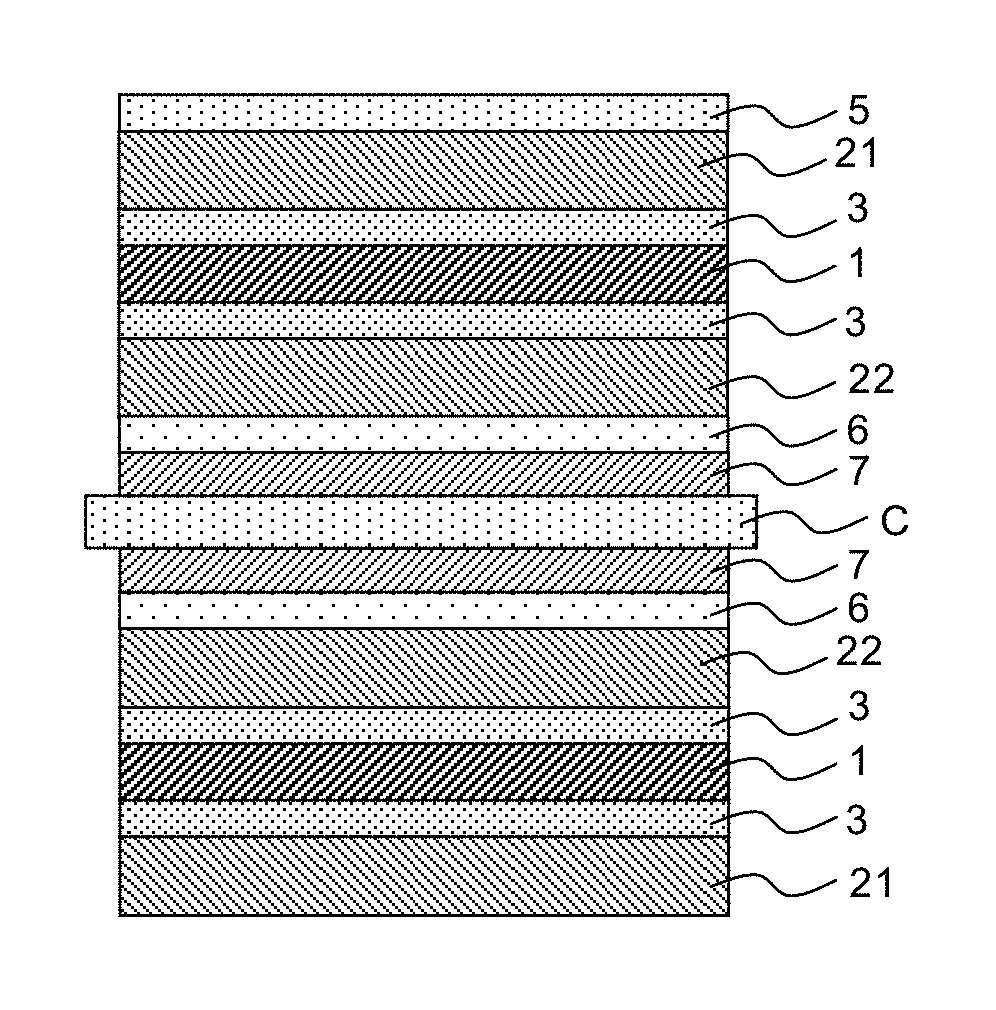
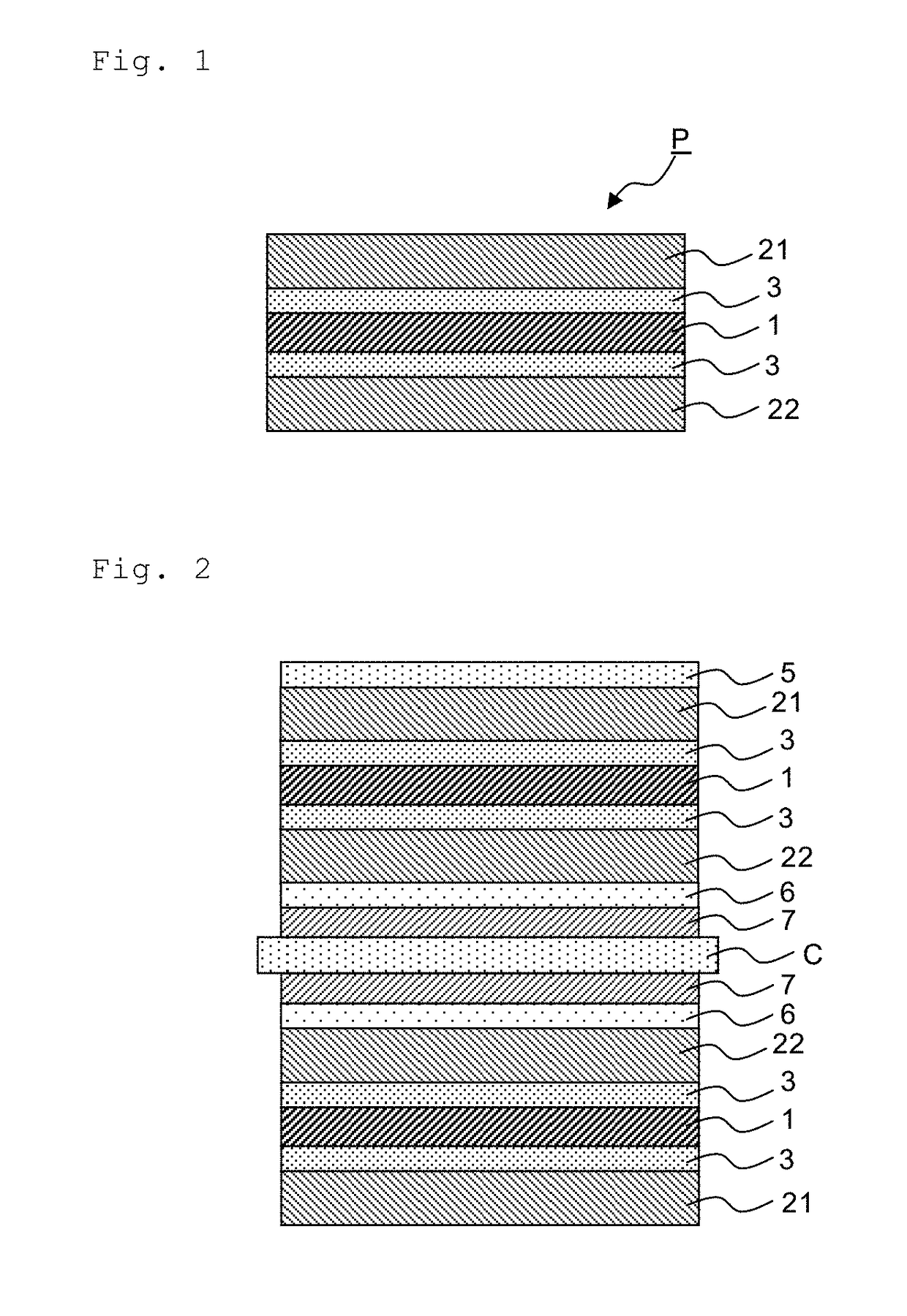
[0161]The adhesive A was applied to one surface of the transparent protective film A so as to form an adhesive layer with a thickness of 80 nm after drying. The adhesive A was applied to one surface of the transparent protective film H so as to form an adhesive layer with a thickness of 80 nm after drying. The adhesive was applied at a temperature of 23° C., 30 min after its preparation. At a temperature of 23° C., the adhesive-coated transparent protective films A and H were then bonded to both surfaces of the polarizer with a roller machine, and then the laminate was appropriately irradiated with active energy rays from the transparent protective film H side, to cure the adhesive layers A and H located on both the sides, thereby producing a polarizing plate.


PUM

PropertyMeasurementUnit
thickness-direction retardationaaaaaaaaaa
thicknessaaaaaaaaaa
transparencyaaaaaaaaaa

Abstract

A polarizing plate includes: a polyvinyl alcohol-based polarizer; and transparent protective films provided on both surfaces of the polyvinyl alcohol-based polarizer with an adhesive layer interposed between each of the transparent protective films and the polyvinyl alcohol-based polarizer. A first transparent protective film contains a (meth)acrylic resin and an ultraviolet absorber, the (meth)acrylic resin having an unsaturated carboxylic acid alkyl ester unit and a glutarimide unit represented by the general formula (1), having an imidization ratio of 2.5 to 5.0% and an acid value of 0.10 to 0.50 mmol / g, and having an acrylic ester unit of less than 1% by weight. A second transparent protective film contains a cycloolefin-based resin.R1 and R2 each independently represent hydrogen or an alkyl group; and R3 represents an alkyl group, a cycloalkyl group, or an aryl group.

Description

BACKGROUND OF THE INVENTION[0001]Field of the Invention[0002]The present invention relates to a polarizing plate and a liquid crystal display device.[0003]Description of the Related Art[0004]A liquid crystal display device uses liquid crystal switching to visualize the polarization state. Based on the display principle, the liquid crystal display device uses a polarizing plate in which a transparent protective film is bonded to each of both surfaces of a polarizer with an adhesive layer interposed therebetween. Iodine polarizers made of stretched polyvinyl alcohol to which iodine is adsorbed have high transmittance and high degree of polarization. Therefore, they are most popular polarizers widely used as the polarizer. A transparent protective film having a high water vapor permeability such as a triacetylcellulose film is used.[0005]Image display devices such as a liquid crystal display device to which the polarizing plate is applied are used under various environments. Therefore,...

Claims


Application Information

Patent Timeline
Patent Type & Authority Patents(United States)
IPC IPC(8): G02B5/30G02B1/14G02B1/16G02F1/1335
CPCG02B1/14G02B1/16G02B5/305G02B5/3033G02B5/3083G02F1/133528G02B1/04C08L29/04C08L33/26C09D5/16C09J9/02G02B5/003G02B5/208G02B5/3041G02F1/1335
Inventor NAKATA, MIEMURAYAMA, SHUNSUKEYAMASHITA, TOMOHIROKIMURA, MAKIKO
Owner NITTO DENKO CORP
Why Eureka
Try Eureka