Multilayer optical recording medium and optical recording method

Inactive Publication Date: 2009-06-18
RICOH KK
View PDF10 Cites 3 Cited by
  • Summary
  • Abstract
  • Description
  • Claims
  • Application Information

AI Technical Summary

Benefits of technology

[0017]The present invention aims at providing a multilayer optical recording medium where a sufficient heat release effect is obtainable even when a thickness of a reflection layer in each information layer other than the innermost information layer as seen from a side of laser light irradiation is ultrathin, a modulation degree is increased to enhance recording per

Problems solved by technology

There are still many problems for this dual layer phase change optical recording medium.
However, in the optical recording medium having two layers or more of the recording layers and the reflection layers, their optical absorption and optical transmission affect, and the reflectance ratio of the optical recording medium itself becomes low.
Thus, in the case o

Method used


Image

  • Multilayer optical recording medium and optical recording method
  • Multilayer optical recording medium and optical recording method
  • Multilayer optical recording medium and optical recording method

Examples


Example

EXAMPLES 1 TO 21 AND COMPARATIVE EXAMPLES 1 TO 5

[0130]A recording line speed when recorded in the first recording layer was 9.2 m / s. Random recordings were performed repeatedly 10 times (DOW 10) on three tracks, and the middle track among them was replayed. The random recording means that 10 type marks of 3T to 11T and 14T and space are irregularly recorded.

[0131]In the evaluation criteria, the recording power where the light transmittance in the first information layer was 40% or more and the modulation degree was saturated was rendered the optimal recording power Ppo[mW], the modulation degree when recorded in the first information layer by Ppo was M (DOW 10) and a crystalline reflectance ratio after recording was Itop (DOW 10). The case of “M≧0.55 and Itop×M≧4.0%” was determined as A, the case of “M≧0.55 and 4.0%

[0132]Evaluation results were collectively shown in Table 2.

Example

Example 1

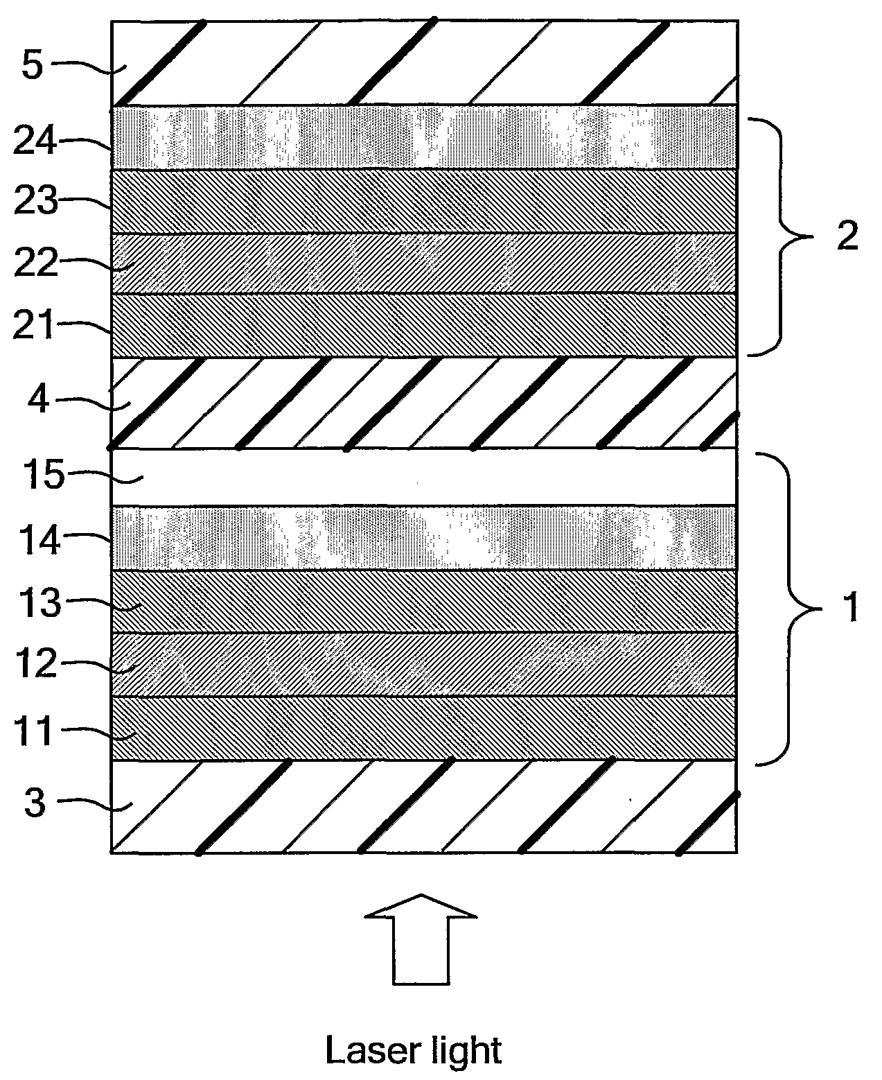
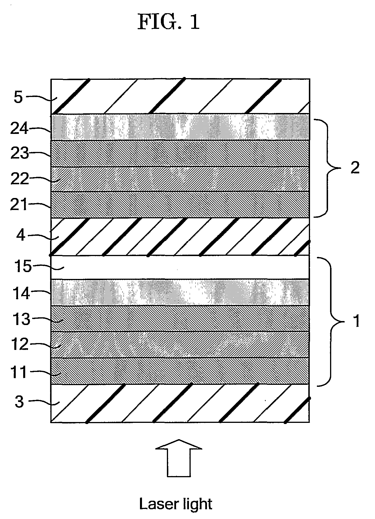
[0133]A first information layer was made by forming a first lower protection layer with a thickness of 60 nm composed of ZnS (80 mol %)-SiO2 (20 mol %), a first recording layer with a thickness of 7.6 nm composed of Ag0.2In3.5Sb69.2Te21.1Ge6, a first upper protection layer with a thickness of 5 nm composed of In2O3 (7.5 mol %)-ZnO (22.5 mol %)-SnO2 (60 mol %)-Ta2O5 (10 mol %), a first reflection layer with a thickness of 8 nm composed of a material in which Mo at 1.1% by mass had been added to Cu and an optical transmission layer with a thickness of 80 nm composed of In2O3 (7.5 mol %)-ZnO (22.5 mol %)-SnO2 (60 mol %)-Ta2O5 (10 mol %) in this order in an Ar gas atmosphere by the spattering method on a first substrate composed of a polycarbonate resin with a diameter of 12 cm and a thickness of 0.58 mm having asperity of a tracking guide formed of continuous groove with a track pitch of 0.74 μm on one side.

[0134]A second information layer was made by forming a second reflecti...

Example

Example 2

[0137]A dual layer phase change optical recording medium was made in the same way as in Example 1 except that the thickness of the optical transmission layer in the first information layer was changed to 60 nm in Example 1. The light transmittance in the first information layer after the initialization was 43.8%.


PUM


Abstract

A multilayer optical recording medium including at least multiple information layers having at least a phase change recording layer capable of recording information by laser irradiation and a reflection layer, wherein information layer as seen from a side of the laser irradiation has at least a lower protection layer, the phase change recording layer, an upper protection layer, the reflection layer and an optical transmission layer, the upper protection layer and the optical transmission layer in each information layer other than the innermost one are composed of an Sn oxide-containing material and a thickness of the upper protection layer in each information layer other than the innermost one as seen from the side of the laser irradiation is 2 nm to 15 nm is provided.

Description

TECHNICAL FIELD[0001]The present invention relates to a multilayer optical medium (hereinafter, also sometimes referred to as “multilayer phase change information recording medium”, “multilayer phase change optical recording medium”, “multilayer optical disc” and a “multilayer phase change optical disc) capable of recording the information by causing optical change in a recording layer material by irradiation of laser light and having multiple recording layers containing a phase change recording layer capable of rewriting the information, and an optical recording method in the optical recording medium.BACKGROUND ART[0002]In phase change optical discs (phase change optical recording media) such as CD-RW, generally a basic constitution is made by providing a recording layer composed of a phase change material on a plastic substrate and thereon forming a reflection layer which enhances an optical absorption ratio of the recording layer and has a thermal diffusion effect, and the inform...

Claims


Application Information

Patent Timeline
IPC IPC(8): B32B3/02G11B7/2403G11B7/24038G11B7/24067G11B7/243G11B7/253G11B7/2534G11B7/257G11B7/2578G11B7/258G11B7/259G11B7/2595
CPCG11B7/0062G11B2007/25716G11B7/24038G11B7/24067G11B7/252G11B7/2534G11B7/2578G11B7/258G11B7/259G11B7/2595G11B2007/0013G11B2007/24308G11B2007/2431G11B2007/24312G11B2007/24314G11B2007/24316G11B2007/25706G11B2007/25708G11B2007/2571G11B2007/25711G11B2007/25713G11B2007/25715G11B7/2403G11B7/254G11B7/257
Inventor SEKIGUCHI, HIROYOSHISHINOTSUKA, MICHIAKISHINKAI, MASARUHIBINO, EIKO
Owner RICOH KK
Why Eureka
Try Eureka