Reflective polarizer and backlight unit including same

Active Publication Date: 2018-06-21
TORAY ADVANCED MATERIALS KOREA
View PDF7 Cites 3 Cited by
  • Summary
  • Abstract
  • Description
  • Claims
  • Application Information

AI Technical Summary

Benefits of technology

The present invention provides a reflective polarizer that can show uniform brightness across the visible light range. It minimizes the mismatch in refractive index and ensures that targeted polarized light within the range transmits through it without bias. This results in an exterior that is not colorful or showing a specific color. The untargeted polarized light within the range is reflected off the reflective polarizer with high reflectivity, ensuring it is not biased towards a specific wavelength range. This technology is useful in applications such as backlight units for display screens.

Problems solved by technology

The optical films used in the LCD do not necessarily have a high utilization efficiency of light emitted from a backlight unit.
The mismatch according to the difference between the refractive indexes of the two non-elongated axes causes a problem in that transmittance of targeted polarized light to be transmitted through the reflective polarizer may be reduced or transmittance of untargeted polarized light may be increased.
However, in conventionally researched and developed reflective polarizers, transmittance of polarized light is reduced in a specific wavelength range of the visible light wavelength range, the reduction of the transmittance in the specific wavelength range makes the transmittance of polarized light in another wavelength range in which transmittance is not reduced relatively high, and thus there is a problem in that an exterior of the reflective polarizer is realized with a color in a wavelength range of a relatively high transmittance.
Particularly, as the above-described problems significantly occur in the light incident on the reflective polarizer in a non-normal line, it is very difficult to adjust a color of a display due to such a problem, and a color feeling realized through the display becomes very poor.
Further, due to the reduction of the transmittance of the light in the specific wavelength range, targeted polarized light reaching the liquid-crystal assembly may be reduced so that problems such as brightness decrease and the like may occur.
Such a reflective polarizer is prevented from appearing the exterior red but the exterior of the reflective polarizer may still appear blue or yellow, and an increase of transmittance of light occurred in a wavelength range of a specific color may still not address difficulty in adjusting a color of a display.
However, the exterior of the reflective polarizer having the transmittance spectra for each wavelength as shown in FIG. 1 may appear to be blue or yellow in color, so that there is still difficulty in controlling the color of the display.
Also, as can be seen from FIG. 1, it can be seen that the transmittance of the light in the wavelength range of 400 to 600 nm except for about 450 nm is significantly reduced to be less than 80% thereof, and the decrease of the transmittance may cause a problem that an intensity of P-polarized light reaching an LCD is reduced and brightness of the display is significantly reduced.
Further, in S-polarized light (which corresponds to c of FIG. 1, and c represents transmittance of polarized light parallel to extinction axis when light is incident in a normal line) which should be reflected without reaching the LCD, some wavelength ranges of wavelength ranges of visible light have excellent reflectivity but the other wavelength ranges have significantly reduced reflectivity, reflectivity for each wavelength band is not uniform so that brightness in a specific wavelength band may be significantly reduced and a color modulation phenomenon may be more difficult to control.

Method used


Image

  • Reflective polarizer and backlight unit including same
  • Reflective polarizer and backlight unit including same
  • Reflective polarizer and backlight unit including same

Examples


experimental example 1

[0148]The following physical properties were evaluated for the reflective polarizers manufactured through the above example and the comparative example, and results thereof are shown in Table 1.

[0149]1. Measurement of transmittance of first polarized light and second polarized light according to 45° non-normal line incidence and 90° normal line incidence

[0150]In order to measure the transmittance, a polarimeter (Jasco V7100) was used. Specifically, a sample cell was mounted on an apparatus at 45° and 90° with respect to incident light, and then the transmittance and the polarization degree of the first polarized light and the second polarized light for each wavelength were measured.

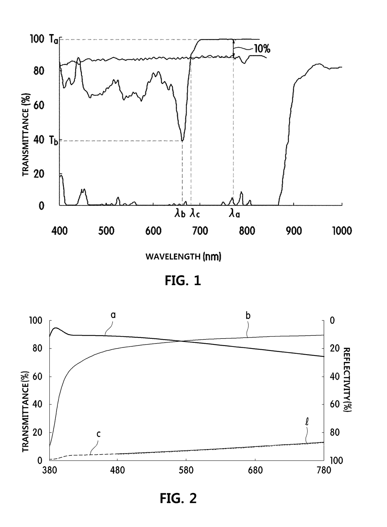
[0151]Further, the transmittance of the first polarized light and the second polarized light at 45° incident angle for each wavelength in Example 1 are shown in FIG. 2.

[0152]2. Relative Brightness

[0153]The brightness of the manufactured reflective polarizer was measured as follows. Panels were assembled o...


PUM


Abstract

The present invention relates to a reflective polarizer and a backlight unit including same and, more particularly, to a reflective polarizer and a backlight unit including same which can display excellent and uniform brightness throughout the visible light wavelength range in the following manner. Regardless of the incident angle of incident light, a discordance in the refractive index in one particular direction is minimized, and the transmissivity of polarized light targeted within the visible light wavelength range is uniform. Thus, light transmitted through the reflective polarizer is not biased toward a particular wavelength range, and the exterior is not colorful or a particular color due to rainbow-colored light. Because the reflectivity of polarized light not targeted within the visible light wavelength range is significantly large, the light is not biased toward a particular wavelength range.

Description

FIELD OF THE DISCLOSURE[0001]The present invention relates to a reflective polarizer and a backlight unit including the same, and more particularly, to a reflective polarizer which can exhibit excellent and uniform brightness throughout a visible light wavelength range in the following manner, and a backlight unit including the same. Regardless of normal line incidence and non-normal line incidence of light, a mismatch in a refractive index in one specific axial direction is minimized and transmittance of targeted polarized light within the visible light wavelength range is uniform. Thus, light transmitted through the reflective polarizer is not biased toward a specific wavelength range, and an exterior is not colorful like rainbow-color or does not show a specific color. Because reflectivity of untargeted polarized light within the visible light wavelength range is significantly large, the light is not biased toward a specific wavelength range.DESCRIPTION OF RELATED ART[0002]Flat p...

Claims


Application Information

Patent Timeline
IPC IPC(8): G02B5/30G02F1/1335
CPCG02B5/30G02F1/133602G02F1/133528G02F1/133536G02F1/13362G02B5/3025G02B6/0056
Inventor KO, SEUNG JINCHO, DUK JAELEE, HWANG KYU
Owner TORAY ADVANCED MATERIALS KOREA
Why Eureka
Try Eureka