Microfluidic devices and uses thereof

a microfluidic device and microfluidic technology, applied in fluid controllers, biochemistry apparatus and processes, laboratory glassware, etc., can solve the problems of difficult control, extremely limited on-chip valving and pumping options,

Inactive Publication Date: 2012-06-28
INTEGENX
View PDF0 Cites 93 Cited by
  • Summary
  • Abstract
  • Description
  • Claims
  • Application Information

AI Technical Summary

Benefits of technology

[0006]The invention provides for a device comprising a cartridge; a microfluidic chip having one or more microfluidic diaphragm valves, fluidically interfaced with the cartridge; and a base co

Problems solved by technology

Typically, microfluidic platforms have utilized conventional lithography with hard materials and have relied on electrokinetic or pressure-based fluid transport, both of which are difficult to control and provi

Method used


Image

  • Microfluidic devices and uses thereof
  • Microfluidic devices and uses thereof
  • Microfluidic devices and uses thereof

Examples


Embodiment Construction

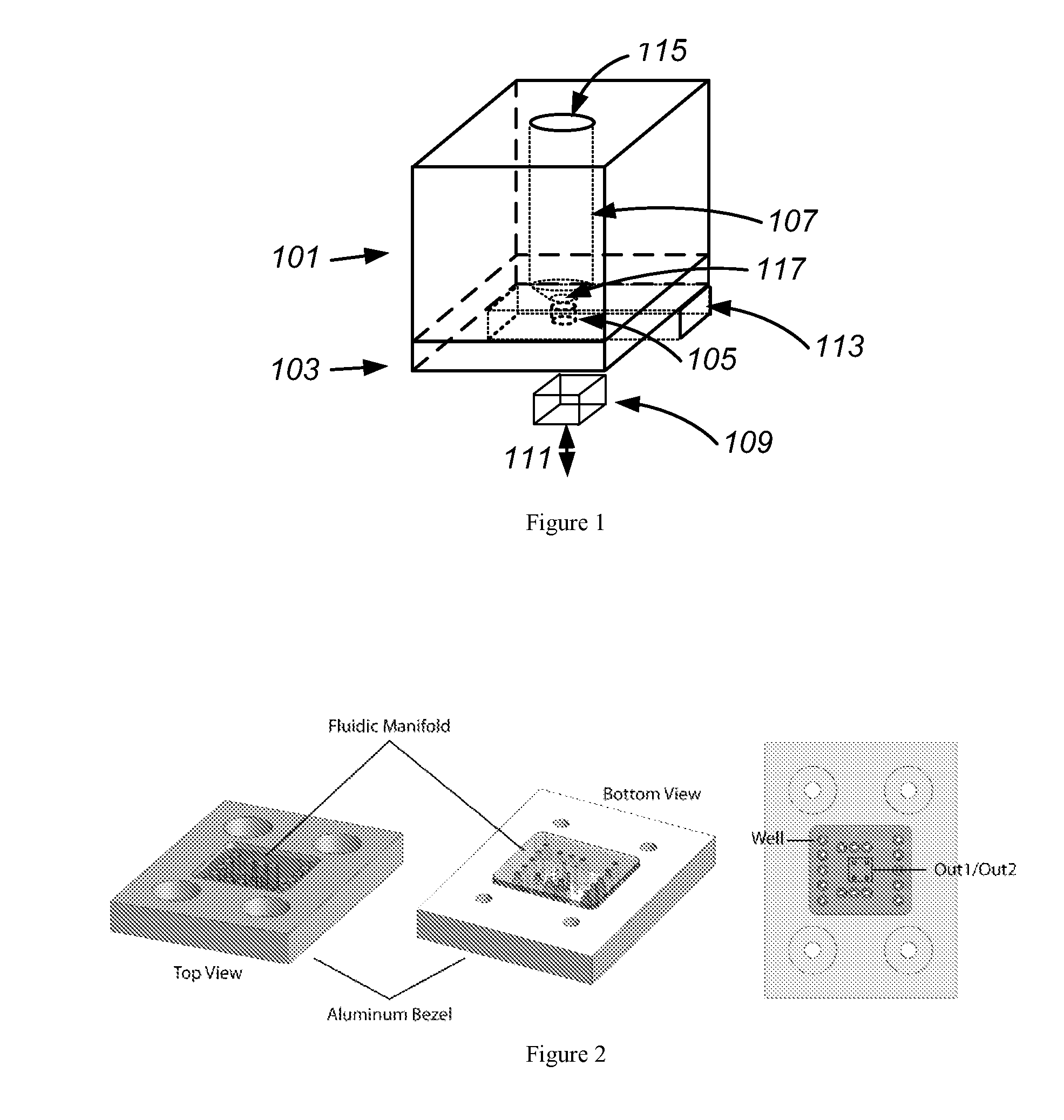
[0060]The invention provides devices for fluid and analyte processing and methods of use thereof. The devices of the invention can be used to perform a variety of actions on the fluid and analyte. These actions can include moving, mixing, separating, heating, cooling, and analyzing. The devices can include multiple components, such as a cartridge, a microfluidic chip, and a pneumatic manifold. FIG. 1 shows an exemplary device having a cartridge (101), microfluidic chip (103), and pneumatic manifold (113). These devices can be used to prepare samples for analysis by gene expression microarrays and to perform biochemical and enzymatic reactions for other purposes.

I. Device Components

A. Cartridges

[0061]A cartridge, also referred to as a fluidic manifold herein, can be used for a number of purposes. In general, a cartridge can have ports that are sized to interface with large scale devices as well as microfluidic devices. Cartridges or fluidic manifolds have been described in U.S. Paten...


PUM


Abstract

The invention provides for devices and methods for interfacing microchips to cartridges and pneumatic manifolds. The design of the cartridges, microchips, and pneumatic manifolds can allow for the use of magnetic forces to capture magnetic beads in a chamber formed between the microchip and the cartridge or a chamber within the microchip. The devices of the invention can be used for mRNA amplification and purification.

Description

[0001]CROSS-REFERENCE[0002]This application claims the benefit of the filing date of U.S. Provisional Patent Application 61 / 227,409 filed on Jul. 21, 2009.STATEMENT OF JOINT DEVELOPMENT[0003]This invention was created pursuant to a joint research agreement between IntegenX, Inc. and Samsung Electronic Co., Ltd.BACKGROUND OF THE INVENTION[0004]Microfluidic platforms have been developed to perform molecular biology protocols on chips. Typically, microfluidic platforms have utilized conventional lithography with hard materials and have relied on electrokinetic or pressure-based fluid transport, both of which are difficult to control and provide extremely limited on-chip valving and pumping options. Other platforms have utilized soft-lithography methods that have been plagued by problems related to absorption, evaporation, and chemical compatibility.[0005]It is therefore desirable to provide improved methods and apparatus for implementing microfluidic control mechanisms such as valves, ...

Claims


Application Information

Patent Timeline
IPC IPC(8): B01L3/00
CPCB01L3/502715B01L3/50273B01L3/502738B01L2400/0481B01L2200/025B01L2300/1822B01L7/52C12M1/34
Inventor STERN, SETHBOGDAN, GREGEBERHART, DAVID
Owner INTEGENX
Why Eureka
Try Eureka