Flat belt

a flat belt and belt technology, applied in the field of flat belts, can solve the problems of flat belts suffering a relatively small energy loss, members stretching or contracting at different ratios, rubber layers and canvas stretching or contracting to different extents, etc., to reduce warping along the belt width of flat belts, stable running of flat belts, and the effect of reducing slipping and snaking

Inactive Publication Date: 2012-06-28
BANDO CHEM IND LTD
View PDF15 Cites 19 Cited by
  • Summary
  • Abstract
  • Description
  • Claims
  • Application Information

AI Technical Summary

Benefits of technology

[0036]The present disclosure enables fabrication of the flat belt which is even without warping along the belt width since the elastic modulus in the belt width direction of the adhesive rubber layer is higher than that of each of the first rubber layer and the second rubber layer. The present disclosure can also reduce the warping along the belt width of the flat belt even when the flat belt wears out or degenerates. As a result, the contact of the flat belt with the pulley substantially in full belt width can be ensured for a long period, and stable running of the flat belt accompanied with reduced slipping and snaking can be achieved.

Problems solved by technology

Being formed thinner than other thick belts such as V-belts, the flat belts suffer a relatively small energy loss caused by bending of the belts.
Specifically, in a flat belt including members made of different materials, temperature changes caused by heating or cooling cause the members to stretch or contract at different ratios.
Consequently, temperature changes caused by running of the flat belt cause the rubber layer and the canvas to stretch or contract to different extents.
This causes the flat belt to suffer warping along a belt width.
This causes the flat belt to suffer warping along the belt width.
This causes the inner rubber layer to suffer uneven wear on a surface in contact with the pulley, and the surface partially wears out.
As a result, the flat belt unstably runs and easily slips to have difficulty in performing a reliable transmission.

Method used


Image

  • Flat belt
  • Flat belt
  • Flat belt

Examples


first embodiment

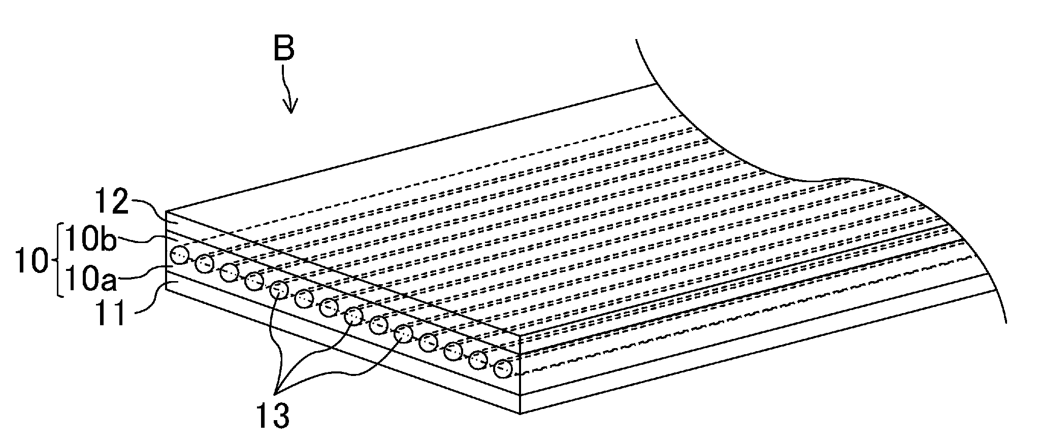
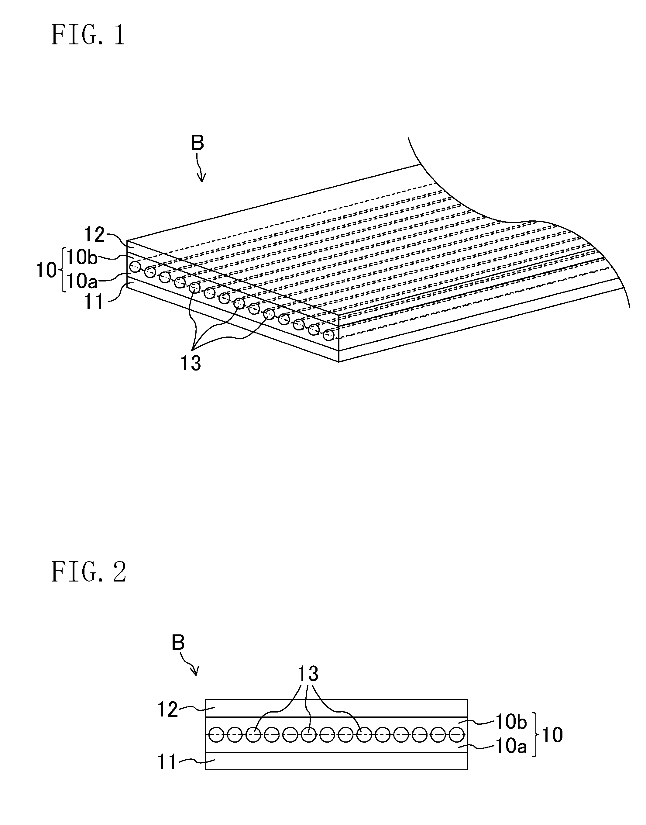
[0042]FIGS. 1 and 2 show a first embodiment of a flat belt according to the present disclosure. FIG. 1 is a perspective cross-sectional view schematically showing a flat belt B of the first embodiment. FIG. 2 is a cross-sectional view schematically showing the structure of the flat belt B.

[0043]As shown in FIGS. 1 and 2, the flat belt B includes an adhesive rubber layer 10 formed in an endless ring shape, an inner rubber layer 11 provided on the inner surface of the adhesive rubber layer 10 and corresponding to the first rubber layer, and an outer rubber layer 12 provided on the outer surface of the adhesive rubber layer 10 and corresponding to the second rubber layer. The inner rubber layer 11 comes into contact with a pulley, around which the flat belt is allowed to run, at the surface opposite to the adhesive rubber layer 10. The flat belt B is formed, for example, to have a width of about 20 mm and a total thickness of about 2.5 mm.

[0044]The inner rubber layer 11 and the outer r...

example

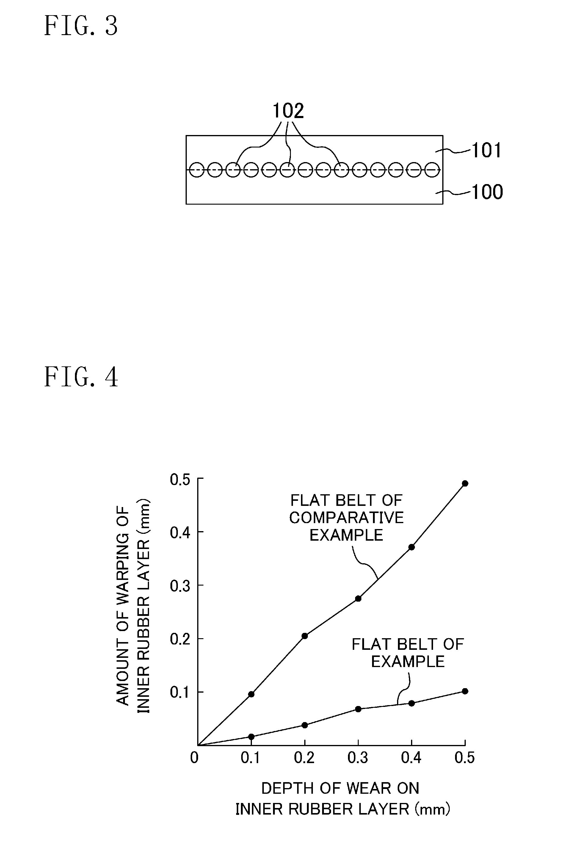
[0066]An example in which the present disclosure works in a concrete manner will be described next. A running test was conducted on a flat belt B of an example of the present disclosure to measure the amount of warping in relation to the depth of wear on an inner rubber layer 11. The amount of warping indicates how much the inner rubber layer 11 of the flat belt B has deformed compared to its original shape.

[0067]The flat belt B of this example has a structure similar to that of the flat belt B of the first embodiment. A tensile cord 13 of the example has a diameter of about 0.5 mm as a whole and is configured of bundled aramid cords each having a diameter of 2400 denier. An adhesive rubber layer 10 contains aramid fibers as the short fibers. In the flat belt B of the example, the inner rubber layer 11, a tensile-cord inner rubber layer 10a, a tensile-cord outer rubber layer 10b and an outer rubber layer 12 are the same as those exemplified in the first embodiment in thickness and i...


PUM

PropertyMeasurementUnit
total thicknessaaaaaaaaaa
widthaaaaaaaaaa
thicknessaaaaaaaaaa

Abstract

A flat belt includes an adhesive rubber layer formed in an endless ring shape and having a tensile member embedded therein, a first rubber layer provided on a surface of the adhesive rubber layer, and a second rubber layer provided on the other surface of the adhesive rubber layer, in which an elastic modulus in a belt width direction of the adhesive rubber layer is higher than the elastic modulus in the belt width direction of each of the first rubber layer and the second rubber layer.

Description

TECHNICAL FIELD[0001]The present disclosure relates to flat belts.BACKGROUND ART[0002]Conventionally, flats belts are broadly known as belts for conveying paper sheets such as paper currencies in automated teller machines (ATMs) and train tickets in automatic ticket gates and for driving main shafts of machine tools, for example. Being formed thinner than other thick belts such as V-belts, the flat belts suffer a relatively small energy loss caused by bending of the belts. Accordingly, the flat belts have transmission efficiency higher than that of V-belts and the like.[0003]The flat belts generally have a laminated structure as a stack of two or more members, which are made of different materials in many cases. The linear expansion coefficient of the member constituting the flat belts varies depending on its material. Specifically, in a flat belt including members made of different materials, temperature changes caused by heating or cooling cause the members to stretch or contract ...

Claims


Application Information

Patent Timeline
Patent Type & Authority Applications(United States)
IPC IPC(8): F16G1/08B65H5/02B65G15/34
CPCB65G15/32B65G15/36B65H5/021B65H2401/111B65H2401/2311F16G1/08B65H2404/27B65H2220/09B65H2701/1912B65H2401/23
Inventor KITANO, YOSHIYUKIINUKAI, MASAHIROTAKAHASHI, MITSUHIKO
Owner BANDO CHEM IND LTD
Why Eureka
Try Eureka