Systems and Methods for Heart and Activity Monitoring

a heart and activity monitoring and activity monitoring technology, applied in the field of system and method for monitoring the heart and activity of a patient, can solve the problems of insufficient alone diagnosis of transplant rejection, heart failure, other heart related disorders, and ineffective ecg in detecting certain heart events, and the current heart monitoring system provides limited heart monitoring capabilities

Inactive Publication Date: 2012-06-28
QRS HEART
View PDF4 Cites 74 Cited by
  • Summary
  • Abstract
  • Description
  • Claims
  • Application Information

AI Technical Summary

Benefits of technology

[0010]In some embodiments, the collected IMEG signals include IMEG signals collected from one or more locations in the patient. In some embodiments, the collected IMEG signals include IMEG signals collected from the right ventricular myocardium and / or the left ventricular myocardium. In some embodiments, the collected IMEG signals include IMEG signals collected from the right ventricular septum of the patient. In some embodiments, the collected IMEG signals include IMEG signals collected from the right ventricular apex of the patient. In some embodiments, the collected IMEG signals include IMEG signals collected from both the right ventricular septum and the right ventricular apex of the patient. In some embodiments, a method according to the present invention includes measuring a time difference (e.g., time delay) between IMEG signals collected from one location of the patient (e.g., right ventricular septum) and IMEG signals collected from a second location of the patient (e.g., right ventricular apex).
[0011]In some embodiments, the IMEG signals are collected using a device implanted in the patient. In some embodiments, the IMEG signals are collected using a device external to the patient. In some embodiments, the IMEG signals are collected using one or more electrode leads coupled to the implanted device. In some embodiments, the collected IMEG signals are unipolar IMEG signals. In some embodiments, the IMEG signals are collected using one or more electrically active unipolar screw-in electrode leads. In some embodiments, the IMEG signals are collected using one or more unipolar screw-in electrode leads having electrically active screws positioned within the myocardium of the patient. In some embodiments, IMEG signals are collected using an electrically active unipolar screw-in electrode lead positioned within the muscle tissue of the right ventricular septum of the patient. In some embodiments, IMEG signals are collected using an electrically active unipolar screw-in electrode lead positioned within the muscle tissue of the right ventricular apex of the patient. In some embodiments, IMEG signals are collected using an electrically active unipolar screw-in electrode lead positioned within the muscle tissue of the right ventricular myocardium and / or the left ventricular myocardium. In some embodiments, the electrode lead(s) includes the accelerometer used to detect the activity level of the patient.

Problems solved by technology

Frequently, the ECG by itself is only one of the many diagnostic tools that the physician has in his / her armamentarium, and not adequate alone to diagnose transplant rejection, heart failure, and other heart related disorders.
When cardiac events occur infrequently (paroxysmal occurrences), ECG may not be effective in detecting certain heart events, such as arrhythmias, tachycardia (fast than normal heart rate), bradycardia (slower than normal heart rate), premature ventricular contractions (PVC), bigeminy, trigeminy, or other abnormal rhythms.
Current heart monitoring systems provide limited heart monitoring capabilities.
Other systems are ineffective at detecting problems because of patient movement, respiration, inspiration, and emotional or physiologic stress.
Frequently, traditional methods of heart monitoring are ineffective or incapable of detecting the subtle heart performance metrics that may indicate that heart failure or transplant rejection is present or imminent.

Method used


Image

  • Systems and Methods for Heart and Activity Monitoring
  • Systems and Methods for Heart and Activity Monitoring
  • Systems and Methods for Heart and Activity Monitoring

Examples


example

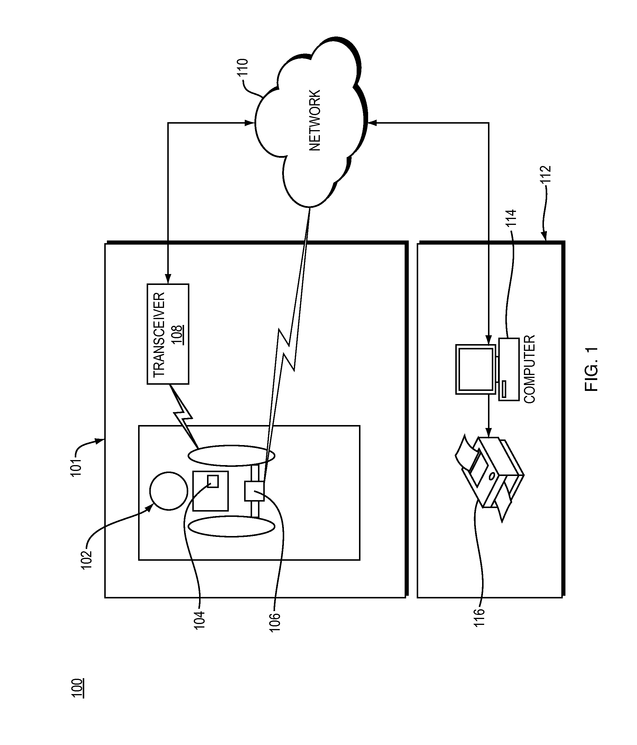
[0197]Each of three canine subjects (Dog 1, Dog 2, and Dog 3) was implanted with an Implantable Cardiac Assessment Monitor (ICAM) heart monitoring device in accordance with embodiments of the present invention. The heart monitoring devices were coupled to screw-in electrode leads positioned to record IMEG signals from the right ventricular septum (Septal IMEG) and right ventricular apex (Apical IMEG).

[0198]Microembolization procedures were performed on two of the subjects (Dog 1 and Dog 3) in order to induce heart failure (HF) over time, while the third subject (Dog 2) was selected as a control animal and did not undergo embolization. Embolization was performed by injecting silicone microspheres into the arteries of Dog 1 and Dog 3 in order to reduce blood flow to portions of the subjects' hearts, thereby causing infarction.

[0199]Cardiac data as described herein were recorded by the implanted heart montioring devices and transmitted wirelessly to external bedside montiors, which in ...


PUM


Abstract

Methods and systems for monitoring a heart failure or transplant rejection status of a patient including use of a device or system to collect intramyocardial electrogram (IMEG) signals from the patient at different times automatically when a detected activity level of the patient is below a preset threshold level for a predetermined amount of time, and use of a device or system to generate a status indicator value proportional to a combination of parameters extracted from at least a portion of the collected IMEG signals. Methods and systems can also include measuring time delay values between IMEG signals collected from different locations in the patient. The IMEG signals can be collected from the right ventricular septum and the right ventricular apex of the patient or from the right and left ventricular myocardium of the patient.

Description

CROSS-REFERENCE TO RELATED APPLICATIONS[0001]This application is a continuation-in-part of U.S. patent application Ser. No. 11 / 712,284, filed Feb. 27, 2007, which claims the benefit of U.S. Provisional Patent Application No. 60 / 776,834, filed Feb. 27, 2006, each of which are incorporated herein by reference in its entirety. This application also claims the benefit of U.S. Provisional Patent Application No. 61 / 215,956, filed May 13, 2009, and U.S. Provisional Patent Application No. 61 / 240,576, filed Sep. 8, 2009, each of which is incorporated herein by reference in its entirety.TECHNICAL FIELD OF THE INVENTION[0002]The present invention relates, in some embodiments, to systems and methods for monitoring the heart of a patient. In some embodiments, the present invention relates to systems and methods for monitoring the activity of a patient. More particularly, the present invention relates, in some embodiments, to systems and methods for monitoring the heart failure status of a patien...

Claims


Application Information

Patent Timeline
Patent Type & Authority Applications(United States)
IPC IPC(8): A61B5/0205A61B5/11
CPCA61B5/0031A61B5/042A61B5/0452A61B5/1118A61B5/413G06F19/3487A61B5/7275A61B2562/0219G06F19/322G06F19/3406G06F19/345A61B5/6882A61B5/283A61B5/349G16H10/60G16H15/00G16H40/63G16H50/20
Inventor SHOLDER, JASON
Owner QRS HEART
Why Eureka
Try Eureka