Cannula and method of manufacturing the cannula

a manufacturing method and cannula technology, applied in the field of cannulas, can solve the problems of taking time to cure completely, and achieve the effects of reducing the variation of the power required for the operation, and reducing the increase rate of the impalement resistance accompanying the passage of the inclined cut surfa

Inactive Publication Date: 2012-06-28
MATSUTANI SEISAKUSHO CO LTD
View PDF11 Cites 9 Cited by
  • Summary
  • Abstract
  • Description
  • Claims
  • Application Information

AI Technical Summary

Benefits of technology

[0017]In the cannula according to the present invention, an inclined cut surface in which one side of a cylindrical material more protrudes along the cylinder than the other side is formed at an end of the cylindrical material. A tapered surface with uneven width, where the protruding side of the cylindrical material has a larger width than the nonprotruding side, is formed on the outer peripheral surface of the inclined cut surface. Namely, since the width of the tapered surface on the protruding side (the width in a direction along the axis of the cylinder) is larger than the width of the tapered surface on the nonprotruding side, the angle of the tapered surface on the protruding side relative to the axial center of the cylindrical material can be made smaller than the angle of the tapered surface on the nonprotruding side relative to the axial center of the cylindrical material.
[0018]Thus, when the cutting member is inserted through the inside of the cannula, the angle formed by the outer peripheral surface of the cutting member and the tapered surface on the protruding side of the cylindrical member becomes small. Accordingly, when the cannula passes through an incisional wound formed in tissue by the cutting member, the impalement resistance at the time when the protruding side of the inclined cut surface passes can be made small. After the protruding side of the inclined cut surface...

Problems solved by technology

If the tissues are dissected, a problem t...

Method used


Image

  • Cannula and method of manufacturing the cannula
  • Cannula and method of manufacturing the cannula
  • Cannula and method of manufacturing the cannula

Examples


Embodiment Construction

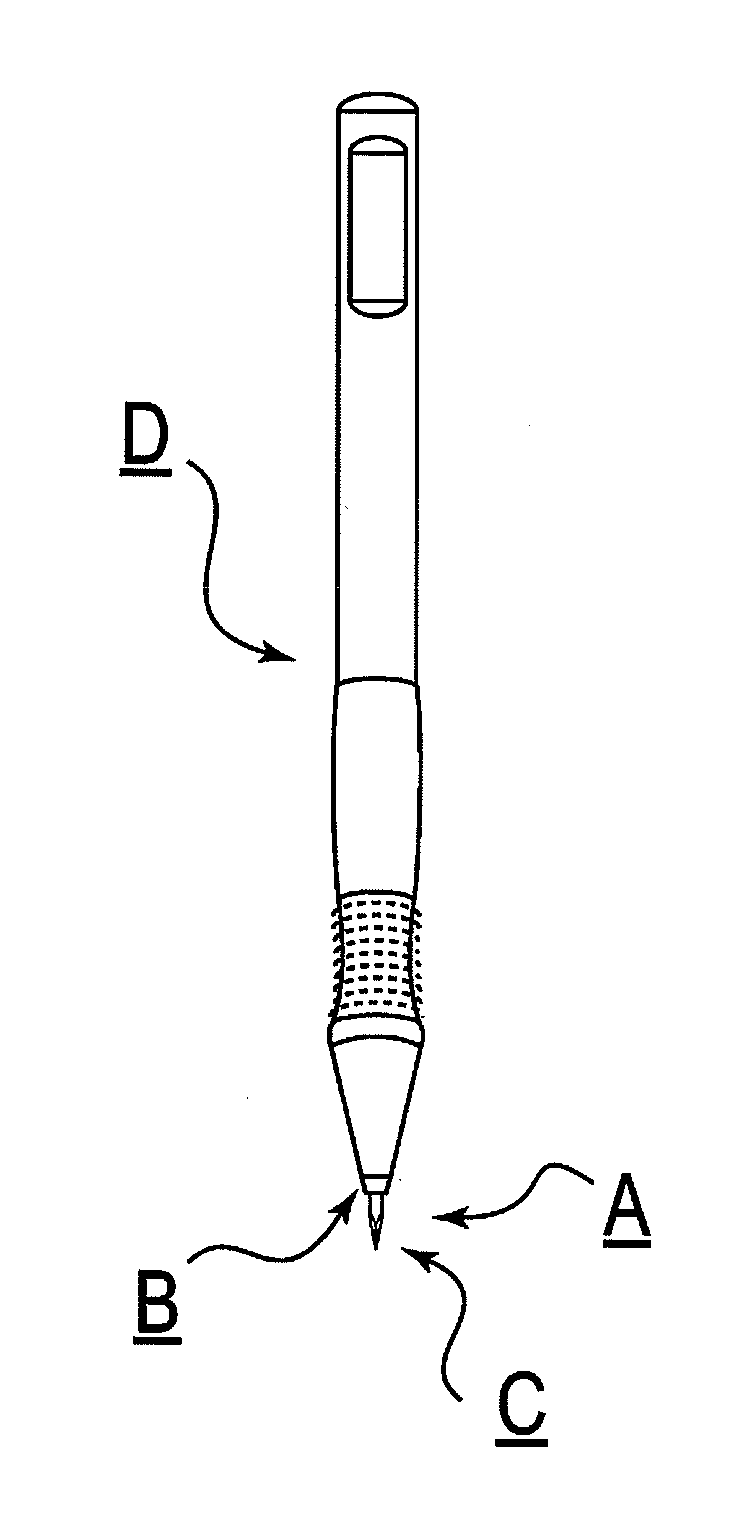
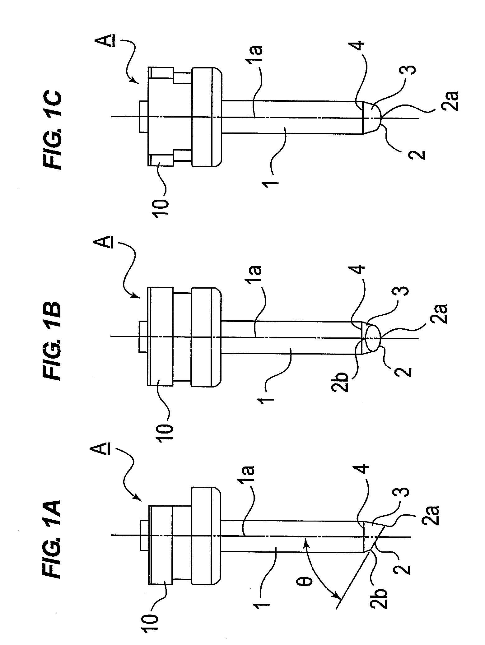
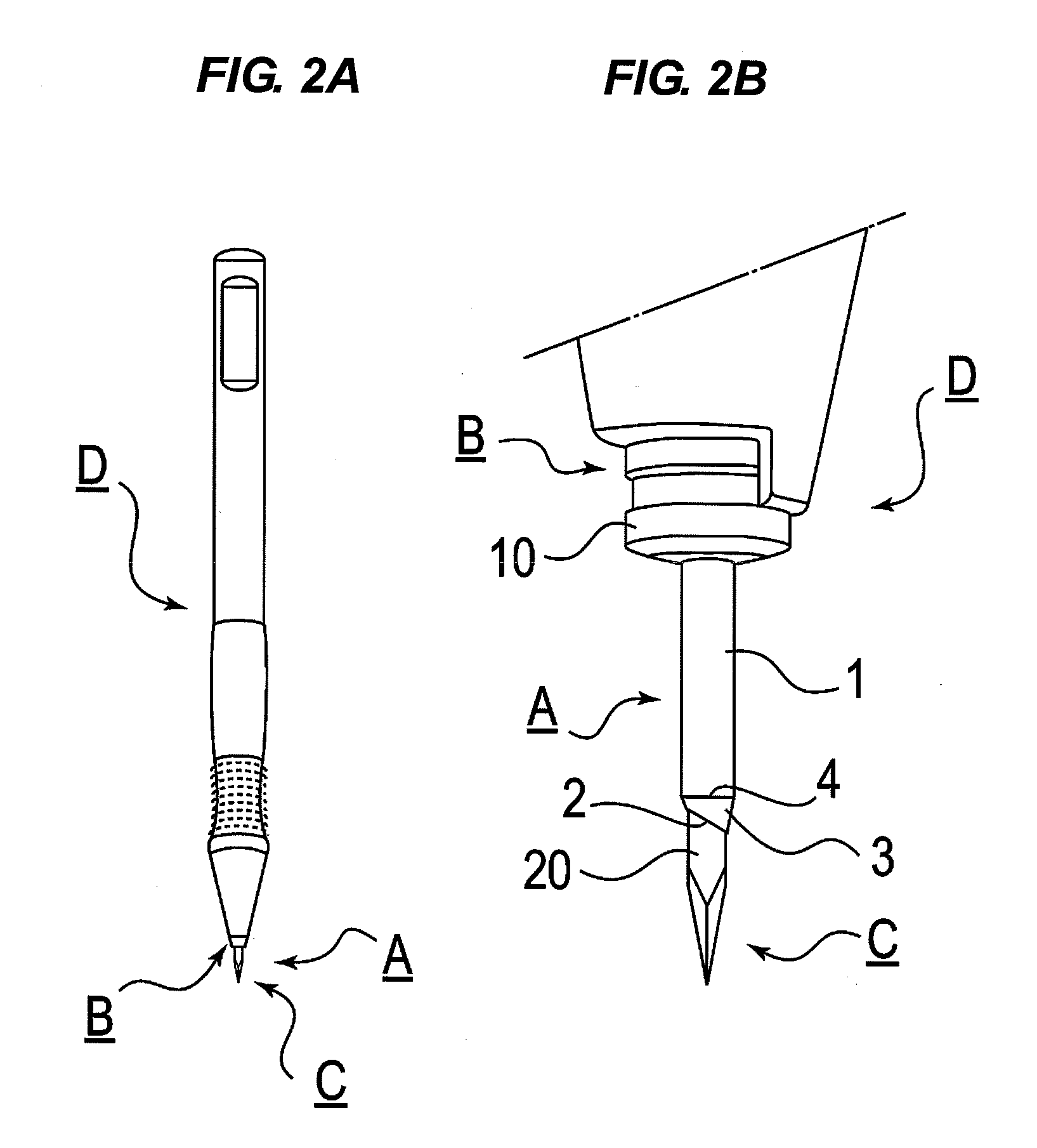
[0045]Hereinafter, a configuration of a cannula according to the present invention and a method of manufacturing the cannula will be described. The cannula according to the present invention constitutes a trocar which forms an incisional wound in tissue by means of a cutting member mounted in a detachably attachable manner and impales the incisional wound to form a passage through which surgical instruments and tubes for injecting chemicals reach an affected area.

[0046]The cannula of the present invention has been made based on the following finding. Namely, when the outer diameter and the inner diameter of the cannula have the same value (the thicknesses are equal to each other), the maximum values of impalement resistance generated when the cannula passes through tissue are the same regardless of the shape of an end of the cannula. However, the rate of the increase in resistance value accompanying increase in a passage length at the time when the end of the cannula passes through ...


PUM

PropertyMeasurementUnit
Electrical resistanceaaaaaaaaaa
Widthaaaaaaaaaa

Abstract

Disclosed is a cannula that can decrease the rate of increase in resistance that is generated when penetrating an incision formed in tissue. The cylindrical cannula (1) configures a trocar (B) used during surgery; an incision member (C) can be inserted and removed therewithin; one side of the end portion of the cylinder forms a protruding slanted cut end (2); and a tapered surface (3) having an uneven width and a width that is wider on the protruding side (the side of point 2a) of the slanted cut end than the non-protruding side (the side of point 2b) is formed on the outer periphery of the slanted cut end (2).

Description

TECHNICAL FIELD[0001]The present invention relates to a cannula, which constitutes a trocar inserted through tissue in surgery and forming a passage through which surgical instruments and tubes for injecting chemicals reach an affected area, and a method of manufacturing the cannula.BACKGROUND ART[0002]A trocar is adapted to have a tubular cannula. A portion of body surface tissue is cut out to make the cannula penetrate and, thus, to arrange the cannula, so that the trocar forms a passage for passing surgical instruments and light fixture required for surgery for the affected area or tubes for injecting chemicals.[0003]In an ophthalmic vitreous surgery, for example, there are used a plurality of trocars including a trocar for inserting a tube for injecting saline for keeping eye pressure, a trocar for inserting surgical instruments typified by forceps and scissors for incising and removing the affected area, and a trocar for inserting a probe for irradiating laser beam to the affec...

Claims


Application Information

Patent Timeline
IPC IPC(8): A61B17/34B24B1/00
CPCA61B17/3421A61B2017/00526A61M5/158A61F9/007A61B2017/3454B24B5/02B24B5/04B24B21/004
Inventor MURAKAMI, ETSUOOGANE, KAORU
Owner MATSUTANI SEISAKUSHO CO LTD
Why Eureka
Try Eureka