Method for determination of gearshift points

a technology of gear shift and point, applied in the direction of digital data processing details, mechanical instruments, instruments, etc., can solve the problems of time-consuming and expensive calibration process, inability to meet calibration requirements, etc., and achieve the effect of avoiding instability

Active Publication Date: 2012-06-28
SCANIA CV AB
View PDF9 Cites 6 Cited by
  • Summary
  • Abstract
  • Description
  • Claims
  • Application Information

AI Technical Summary

Benefits of technology

[0016]A further advantage of the invention is that the shift points can be altered without the gear change logic, e.g. in a control unit, having to risk becoming logically unstable, since the shift points are controlled indirectly via the engine target speed, so the relationship between the shift points can be controlled in such a way as to avoid instability.
[0017]Further advantages and applications of a method and a system according to the invention are indicated by the detailed description set out below.

Problems solved by technology

This procedure for calibration of shift points is both time-consuming and expensive.
Moreover, the results of the calibration are not always satisfactory in that the calibrated shift points may be appropriate for certain driving situations but less so for others.

Method used


Image

  • Method for determination of gearshift points
  • Method for determination of gearshift points
  • Method for determination of gearshift points

Examples


Embodiment Construction

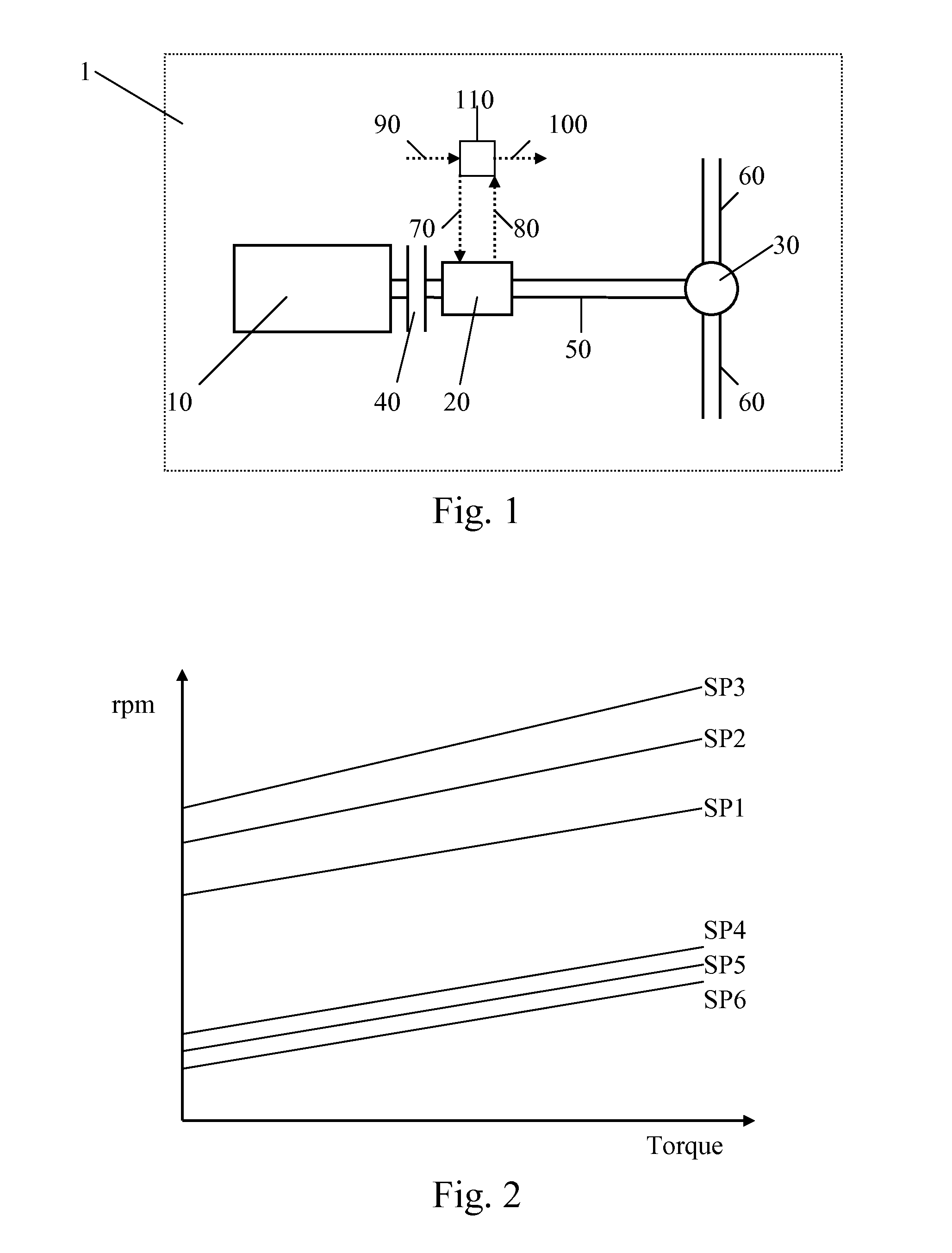
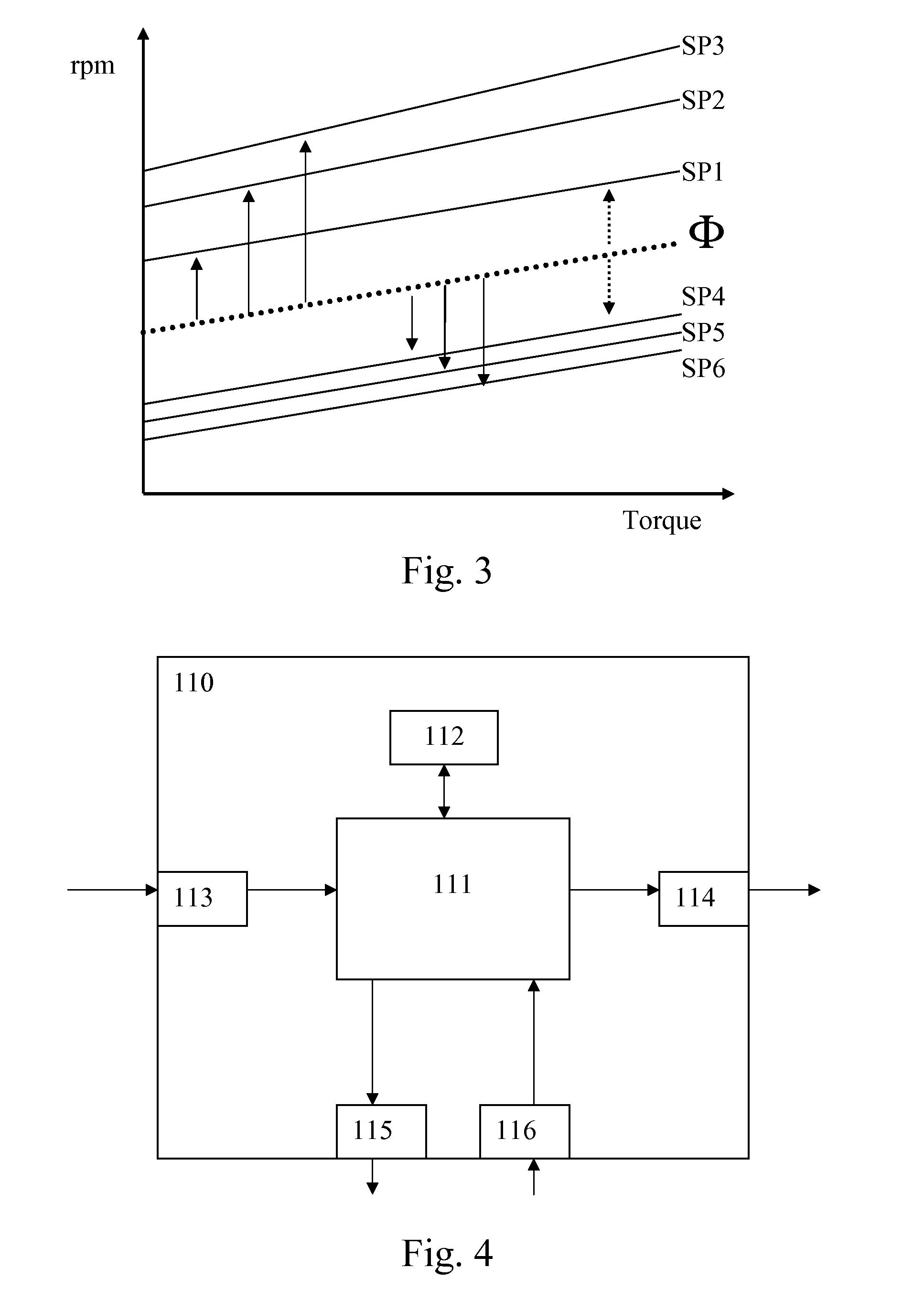
[0023]The present invention relates to determination of one or more downshift and upshift points for a gearbox 20 preferably situated in a motor vehicle 1. A downshift or upshift point represents an engine speed at which the gearbox 20 is respectively adapted to effecting a downshift or upshift. The engine speed for upshift points is higher than the engine speed for downshift points.

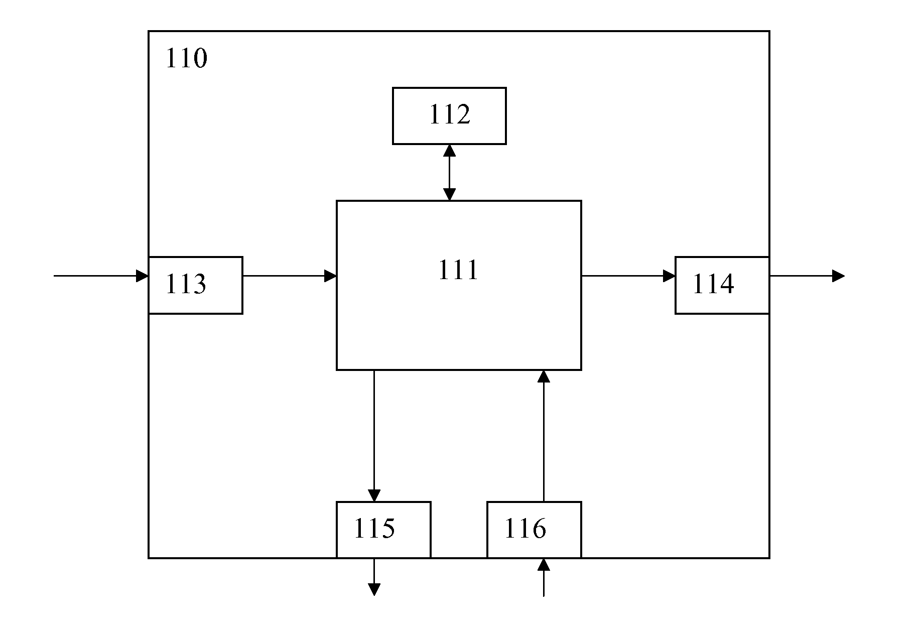
[0024]The gearbox 20 is preferably of the kind which forms part of an automated gear change system controlled by a control unit 110, e.g. an ECU. In such a system, gear changes are effected automatically by the control unit 110 but it is also usual for the driver to be able to execute manual gear changes in such a system, what is known as manual gear change in automatic state (automatic mode). The gearbox 20 also has a plurality of gears, e.g. twelve forward gears and one or more reverse gears are usual in modern trucks.

[0025]According to the invention, the downshift and upshift points are determined rel...


PUM


Abstract

A method for determination of one or more downshift and upshift points for a gearbox in a motor vehicle. The vehicle includes an engine connected to the gearbox, where a downshift point represents a first engine speed at which the gearbox effects a downshift, and an upshift point represents a second engine speed at which the gearbox effects an upshift. One or more downshift and upshift points are determined relative to an engine target speed which is a desired speed for the engine. A system, a motor vehicle, a computer program and a computer program product thereof perform the method.

Description

TECHNICAL FIELD[0001]The present invention relates to a method for determination of one or more downshift and upshift points for a gearbox in a motor vehicle. In particular, the invention relates to a method according to the preamble of claim 1. The invention further relates to a system, a motor vehicle, a computer programme and a computer programme product thereof.BACKGROUND TO THE INVENTION[0002]FIG. 1 depicts schematically parts of a power train for a motor vehicle 1, such as a passenger car or a heavy vehicle, e.g. a truck or bus. The power train comprises an engine 10 mechanically connected by a shaft to a first end of a gearbox 20 via a clutch device 40. The gearbox 20 is also mechanically connected, at its other end, by a propeller shaft 50 to a differential gear 30 associated with a rear axle. The rear axle comprises respective left and right drive shafts 60 which drive the vehicle's powered wheels (not depicted in the diagram).[0003]With this well-known arrangement, the mec...

Claims


Application Information

Patent Timeline
Patent Type & Authority Applications(United States)
IPC IPC(8): G01M13/02B60W30/18
CPCB60W30/19F16H59/18F16H2059/366F16H61/0213F16H59/66B60W10/11F16H59/44F16H2061/0015F16H2061/0234
Inventor SWARTLING, FREDRIKKJELL, ANDERSNYSTROM, TOM
Owner SCANIA CV AB
Why Eureka
Try Eureka