
Short Length Pump Having Brine Resistant Seal and Rotating Wrist Pin and Related Methods

a short-length, brine-resistant technology, applied in the field of short-length pumps, can solve the problems of severe degradation of the power seal, and achieve the effect of facilitating the retention of the cylindrical section

Inactive Publication Date: 2012-07-05
S P M FLOW CONTROL
View PDF9 Cites 28 Cited by
  • Summary
  • Abstract
  • Description
  • Claims
  • Application Information

AI Technical Summary

Benefits of technology

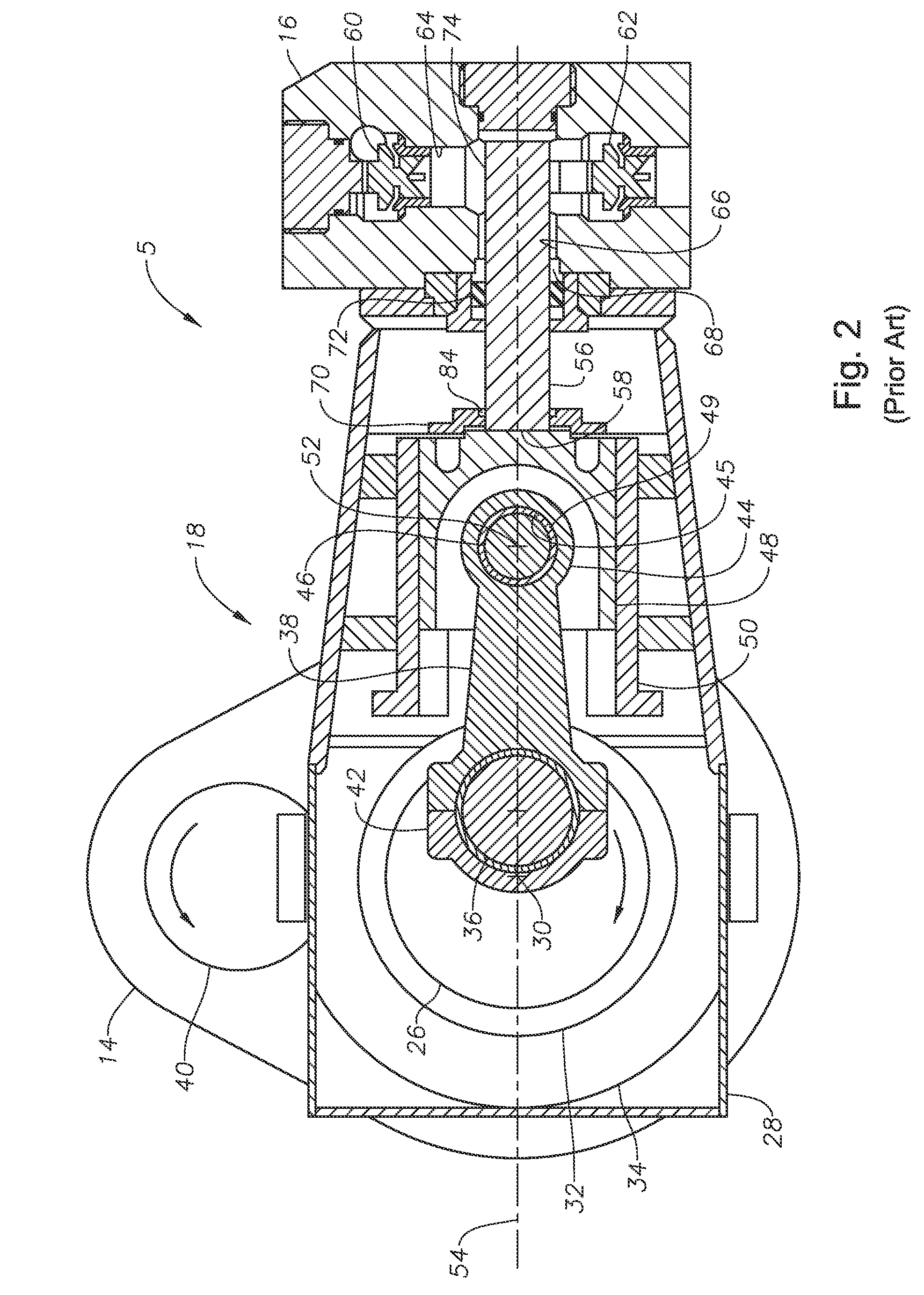
[0012]In certain embodiments, the bushing is in the form of a single arcuate-shaped bushing shaped to extend for at least approximately 180 angle degrees to conform to a corresponding outer surface portion of the wrist pin and a corresponding inner surface portion of the laterally-oriented bore of the crosshead. In other certain embodiments, the bushing is at least partially cylindrically shaped and extends circumferentially for an amount greater than 180 angle degrees to provide for retaining the wristpin within the bushing and the laterally oriented bore, and is substantially less than 360 angle degrees to accommodate for pivotal rotation of the connecting rod resulting from rotation of the crankshaft end of the connecting rod about the crankshaft axis.
[0014]In certain embodiments, the power end seal assembly further includes a splashguard having an elongate cylindrical section positioned at least substantially within the power end seal housing to deflect fluids escaping an output manifold of the pump through an output manifold fluid seal. In certain embodiments, the power end facing surface of the elongate cylindrical section of the splash guard is positioned in contact with a corresponding fluid end facing surface of the power end seal. In certain embodiments, the cylindrical section of the splash guard is further positioned in contact with an inner surface of the power seal housing, an outer surface of the plunger, and a fluid end-facing face of the power end seal. In certain embodiments, the cylindrical section of the splash guard extends at least partially through the aperture of the sealed fluid end-facing side of the power end. In certain embodiments, a conical shaped the lip section is connected to or integral with the cylindrical section of the splashguard to further help deflect fluids leaking from the fluid end section of the pump.
[0015]In certain embodiments, the pump includes a fluid end, a power end having a sealed fluid end-facing side, an annular extension extending toward the fluid end, and a power end seal assembly adjacent the aperture of the sealed fluid end-facing side and including a power end seal housing. The power end seal housing can have an inwardly extending flange, an outwardly extending flange connected to the annular extension, and an elongate main body extending therebetween. In certain embodiments, the power and seal assembly further includes an annular power end fluid seal positioned in contact with a fluid end-facing portion of the inward extending flange, an inner surface of the power seal housing, an outer surface of the plunger, and a power end-facing face of an elongate cylindrical section of a splash guard. In certain embodiments, the power and seal assembly also or alternatively includes a splashguard assembly positioned to help deflect fluid escaping from the fluid section of the pump. The splashguard assembly can include the splashguard and an annular retention plate operable or otherwise configured to urge the cylindrical section of the splashguard into contact with the power end seal which urges the power end seal into contact with the inwardly extending flange. In certain embodiments, the housing further includes and inwardly extending annular stub located adjacent the outwardly extending flange. In certain embodiments, the elongate cylindrical section of the splashguard correspondingly includes an annular recess aligned / alignable with the annular stub so that the annular stub functions to facilitate retaining the cylindrical section of the splashguard within the power end seal housing.

Problems solved by technology

As the power seal is often subject to severe degradation, various attempts have been made to reduce fluid incursions.

Method used


Image

  • Short Length Pump Having Brine Resistant Seal and Rotating Wrist Pin and Related Methods
  • Short Length Pump Having Brine Resistant Seal and Rotating Wrist Pin and Related Methods
  • Short Length Pump Having Brine Resistant Seal and Rotating Wrist Pin and Related Methods

Examples


Embodiment Construction

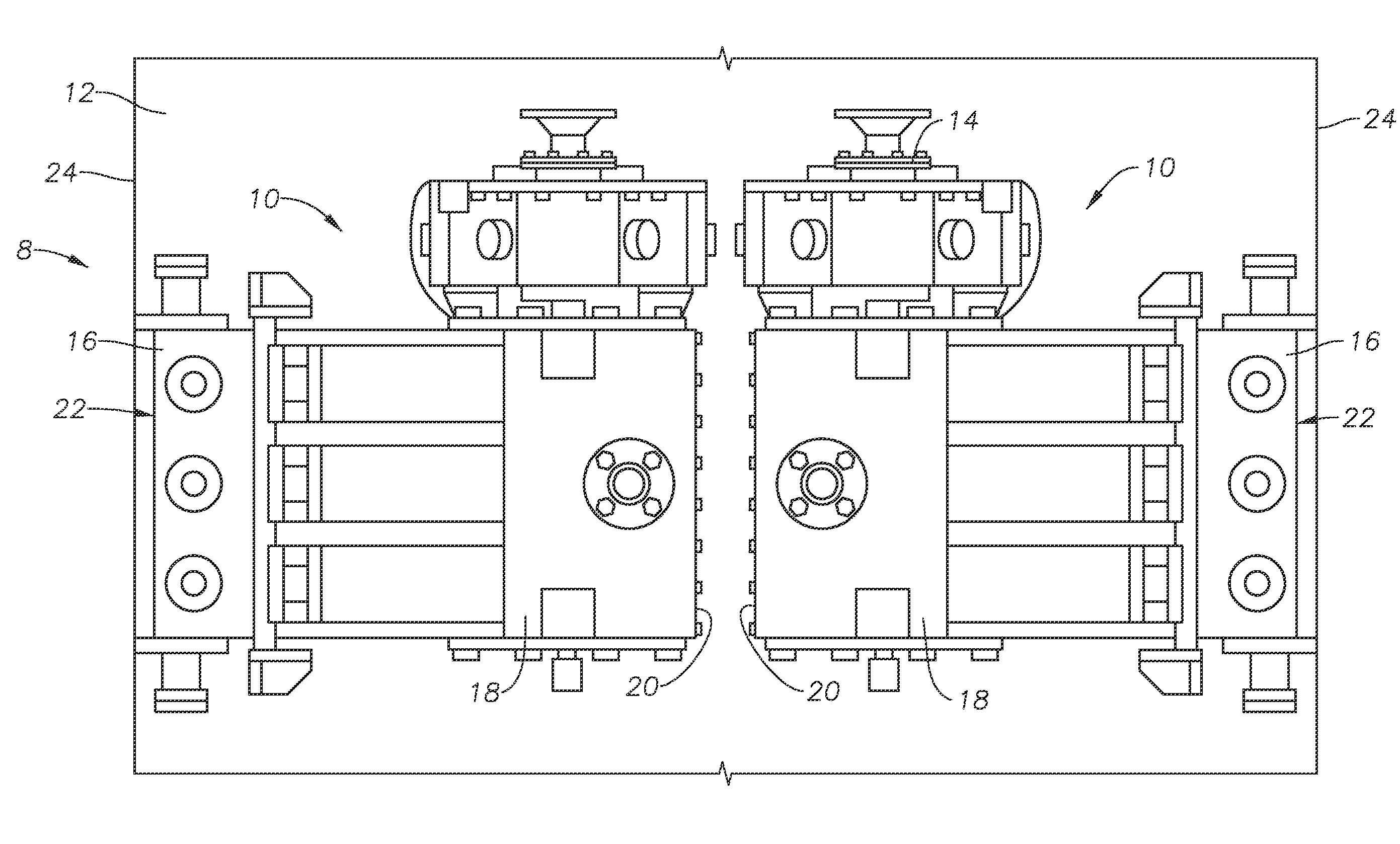
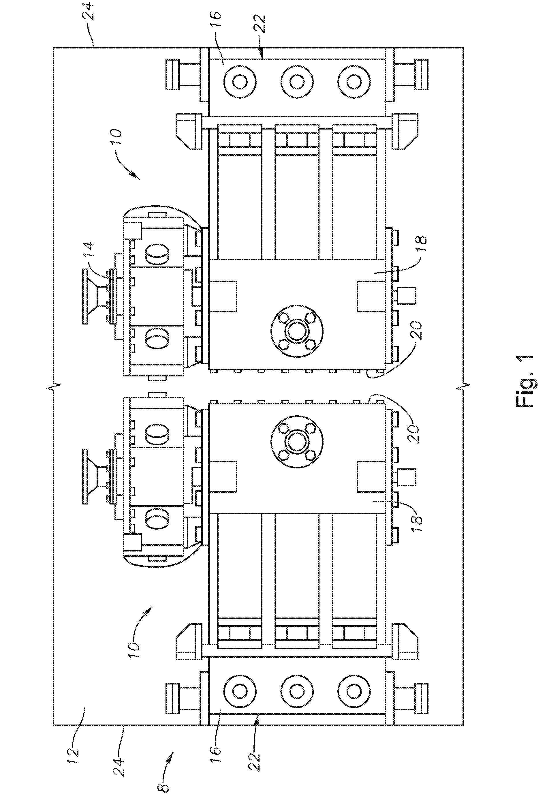
[0028]FIG. 1 is a plan view of a pair of pumps according to one or more aspects of the present disclosure. Specifically, FIG. 1 depicts a pair of pumps 10 (e.g., plunger pump, well service pump) mounted in a back-to-back application. The pumps 10 are typically identical pumps although they may be inverted relative to one another. The pumps 10 may be mounted on a platform 12 (e.g., skid, truck bed, trailer, etc.) together with a prime mover to provide a portable self-contained pumping unit. Depicted in FIG. 1, the skid 12 is a trailer adapted for connecting with a tractor (e.g., truck). The prime mover may be an electric motor or an internal combustion engine, for example. The output of the prime mover is connected to a gear reducer 14. The pumps 10 are depicted as triplex pumps in the depicted embodiment, however, it will be recognized by those skilled in the art with the benefit of the present disclosure that the pumps 10 may comprise more or fewer plungers.

[0029]According to an em...


PUM


Abstract

Pumps and plunger assemblies are provided. An exemplary pump can have or contain a cylinder mounted in a pump housing, a plunger assembly including a crosshead, a plunger, a stationary bushing having substantial portions fixedly mounted within a laterally extending bore of the crosshead, and a non-stationary pivotally rotating wrist pin mounted within the bushing. The pump can also include a power end seal assembly including a seal housing extending at least partially through an aperture in the sealed fluid end-facing side of the power end of the pump, a power end seal disposed therein in sealing contact with the power end section of the plunger and a splashguard assembly.

Description

RELATED APPLICATIONS[0001]This application claims the benefit of and priority to U.S. Provisional Patent Application No. 61 / 427,850, titled “Short Length Pump Having Brine Resistant Seal and Rotating Wrist Pin and Related Methods,” filed on Dec. 29, 2010, incorporated herein by reference in its entirety.TECHNICAL FIELD[0002]This disclosure relates to pumps in general, and short-length pumps in particular.BACKGROUND OF THE DISCLOSURE[0003]Oil and gas wells require servicing such as cementing, gravel packing, and acidizing. All of these services require pumps for pumping fluid down the well. The type of pump used normally for these applications is a reciprocating or positive displacement pump. The pump typically has a crankshaft mounted in a housing and positioned to drive a plunger. The plunger has or otherwise connects to a crosshead that is reciprocally carried within a cylinder in the housing, which reciprocates perpendicular to the crankshaft. A connecting rod connects the cranks...

Claims


Application Information

Patent Timeline
IPC IPC(8): F16J1/00
CPCF16J1/14F04B53/144
Inventor CHINTHAN, GROMICHODILLE, MARK
Owner S P M FLOW CONTROL
Learn More