Intake System for an Internal Combustion Engine

a technology for internal combustion engines and intake systems, which is applied in the direction of combustion engines, combustion-air/fuel-air treatment, and charge feed systems, etc., can solve the problems of long air ducts to and from the charge air coolers, noise and vibration, and long ducts. , to achieve the effect of reducing the transient performance of the internal combustion engine, and reducing the cost of the system

Active Publication Date: 2012-07-05
GM GLOBAL TECH OPERATIONS LLC
View PDF5 Cites 23 Cited by
  • Summary
  • Abstract
  • Description
  • Claims
  • Application Information

AI Technical Summary

Problems solved by technology

The charge air cooler is typically mounted in the under hood area of the vehicle near the coolant radiator and the air conditioner condenser coil (i.e. near the front of the vehicle) which result in air ducts to and from the charge air cooler that are long and subject to packaging, noise and vibration issues.
Seals between the ducts and the various components present opportunities for leakage and the length of the ducts can have a deleterious effect on transient performance of the internal combustion engine.

Method used


Image

  • Intake System for an Internal Combustion Engine
  • Intake System for an Internal Combustion Engine
  • Intake System for an Internal Combustion Engine

Examples


Embodiment Construction

[0014]The following description is merely exemplary in nature and is not intended to limit the present disclosure, application or uses. It should be understood that throughout the drawings, corresponding reference numerals indicate like or corresponding parts and features.

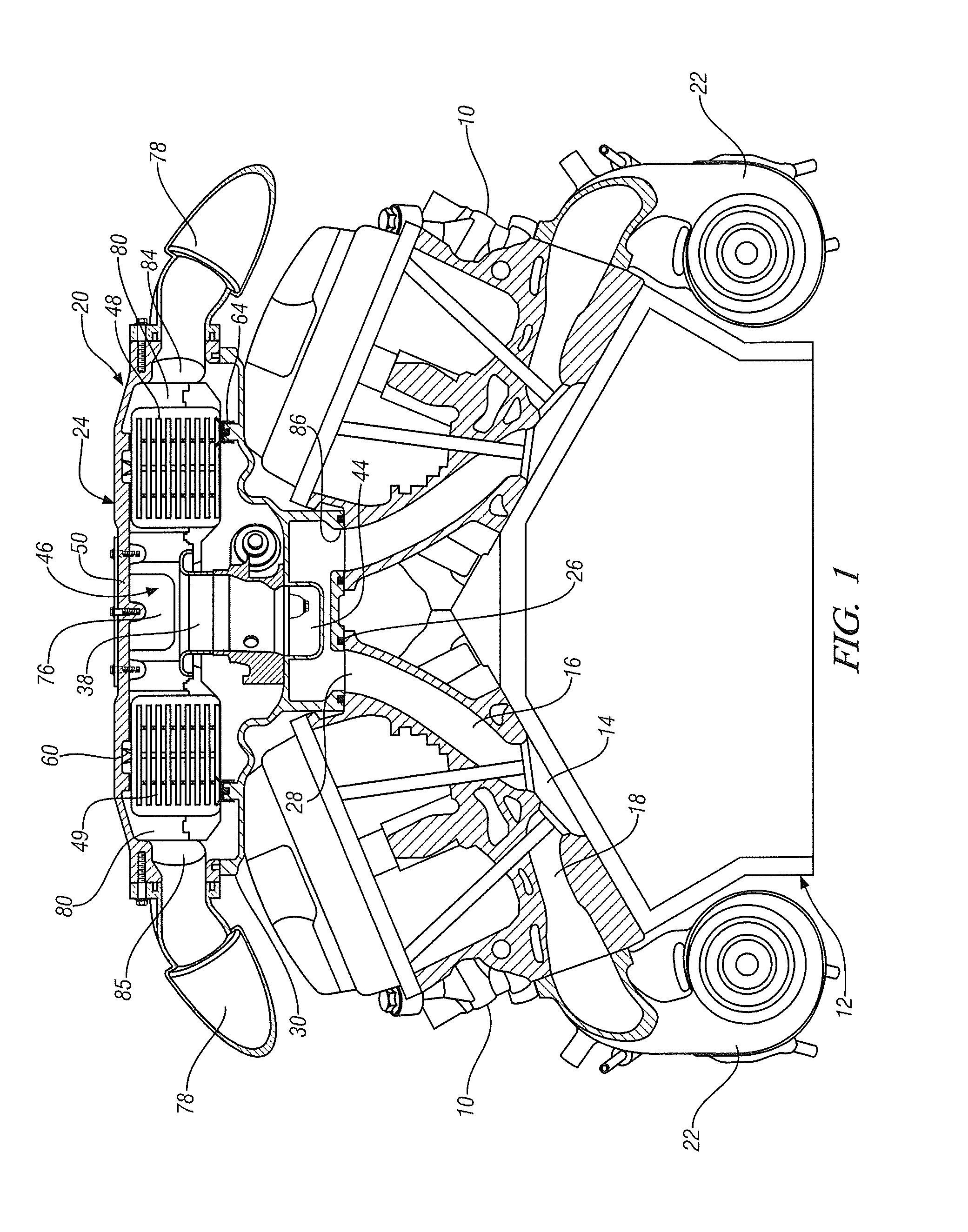
[0015]Referring now to FIG. 1, in an exemplary embodiment, one or more cylinder heads 10 of an internal combustion engine 12 include(s) a plurality of combustion chambers 14 in fluid communication with valved intake ports 16 and exhaust ports 18. The valved intake ports 16 receive combustion air from an air intake system 20 and deliver the intake air to the combustion chambers for mixing with fuel and combustion therein. Products of the combusted air and fuel (i.e. exhaust gas) exit the valved exhaust ports 18 and flow through exhaust driven turbochargers 22 that extract energy from the exhaust gas and utilize it to compress combustion air for delivery to the air intake system 20.

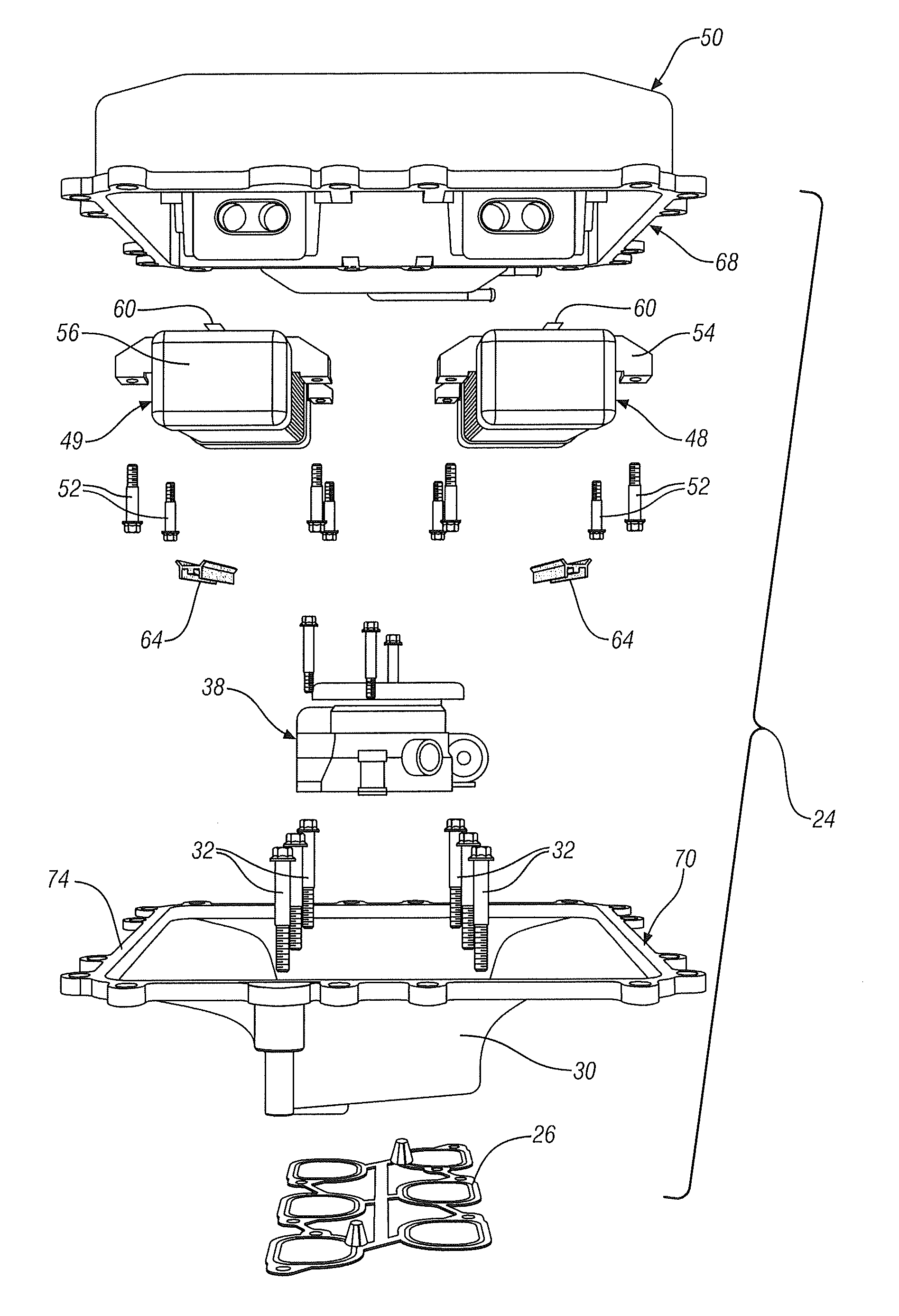
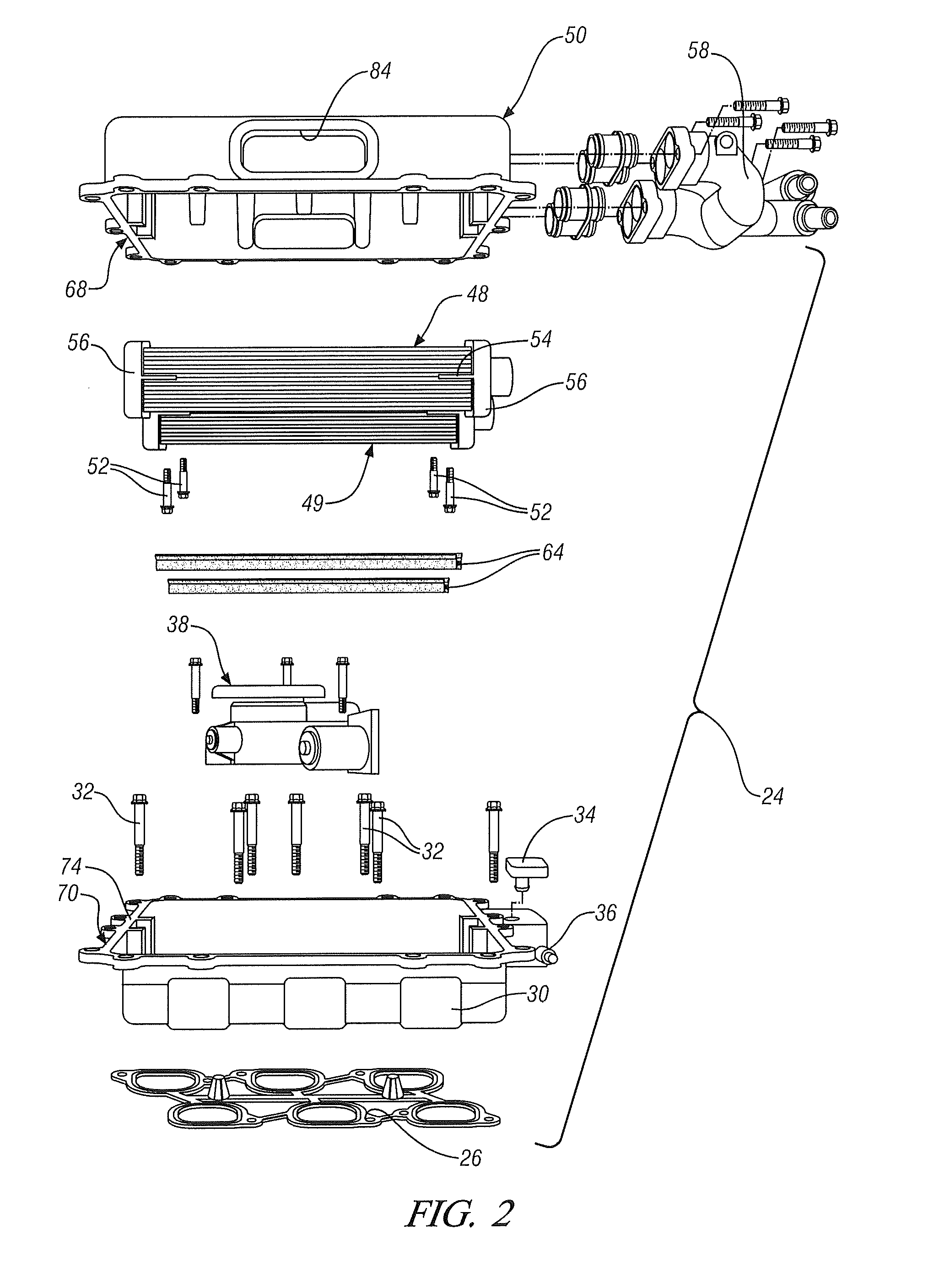
[0016]Referring to FIGS. 1, 2 and 3...


PUM


Abstract

The intake system includes an integrated airflow cooler module comprising a lower manifold assembly and a throttle body fluidly connected to, and disposed within the lower manifold assembly to meter combustion air into a lower manifold volume of the lower manifold assembly. An upper manifold assembly is configured for assembly to the lower manifold assembly to define a manifold volume therebetween and a heat exchanger is disposed in the manifold volume, between the upper manifold assembly and the lower manifold assembly and between a combustion air inlet in the integrated airflow cooler module and the throttle body.

Description

FIELD OF THE INVENTION[0001]Exemplary embodiments of the present invention relate to combustion air intake systems for internal combustion engines and, more particularly, to an intake manifold module incorporating a throttle body, an intake charge cooler, and a manifold.BACKGROUND[0002]Internal combustion engines utilizing charge air compression are typically comprised of one or more exhaust driven turbochargers or an engine driven supercharger to deliver compressed combustion or charge air to the intake manifold. In the case of a dual turbocharger engine configuration, ducts from the turbochargers may combine the compressed combustion air and pass the charge through a charge air cooler. A duct extending from the outlet of the charge air cooler delivers cooled, compressed charge air to a throttle body that is mounted externally to a traditional intake manifold.[0003]The charge air cooler is typically mounted in the under hood area of the vehicle near the coolant radiator and the air...

Claims


Application Information

Patent Timeline
Patent Type & Authority Applications(United States)
IPC IPC(8): F02M31/20
CPCF02B29/0462F02M35/116F02B29/0437F02B29/0412Y02T10/146Y02T10/12
Inventor WONG, KEVIN C.OGALE, SAMEERCLARKE, CHRISTOPHER K.
Owner GM GLOBAL TECH OPERATIONS LLC
Why Eureka
Try Eureka