Heat transfer system utilizing thermal energy storage materials

a heat transfer system and thermal energy storage technology, applied in indirect heat exchangers, machines/engines, lighting and heating apparatus, etc., can solve the problems of more than 30% of the fuel energy supplied to an internal combustion engine (internal combustion engine) being lost to the environment via engine exhaus

Inactive Publication Date: 2012-07-05
DOW GLOBAL TECH LLC
View PDF11 Cites 42 Cited by
  • Summary
  • Abstract
  • Description
  • Claims
  • Application Information

AI Technical Summary

Problems solved by technology

Regarding the transportation industry, it is well known that internal combustion engines operate inefficiently.
Sources of this inefficiency include heat lost via exhaust, cooling, radiant heat and mechanical losses from the system.
It is estimated that more than 30% of the fuel energy supplied to an internal combustion engine (internal combustion engine) is lost to the environment via engine exhaust.
It is well known that during a “cold start” internal combustion engines operate at substantially lower efficiency, generate more emissions, or both, because combustion is occurring at a non-optimum temperature and the internal combustion engine needs to perform extra work against friction due to high viscosity of cold lubricant.
This problem is even more important for hybrid electric vehicles in which the internal combustion engine operates intermittently thereby prolonging the cold start conditions, and / or causing a plurality of occurrences of cold start conditions during a single period of operating the vehicle.
However, they do not provide a long term (>6 hr) heat storage capability, which is desired to mitigate cold start conditions immediately after or even prior to a cold start.

Method used


Image

  • Heat transfer system utilizing thermal energy storage materials
  • Heat transfer system utilizing thermal energy storage materials
  • Heat transfer system utilizing thermal energy storage materials

Examples


Embodiment Construction

[0019]In the following detailed description, the specific embodiments of the present invention are described in connection with its preferred embodiments. However, to the extent that the following description is specific to a particular embodiment or a particular use of the present techniques, it is intended to be illustrative only and merely provides a concise description of the exemplary embodiments. Accordingly, the invention is not limited to the specific embodiments described below, but rather; the invention includes all alternatives, modifications, and equivalents falling within the true scope of the appended claims.

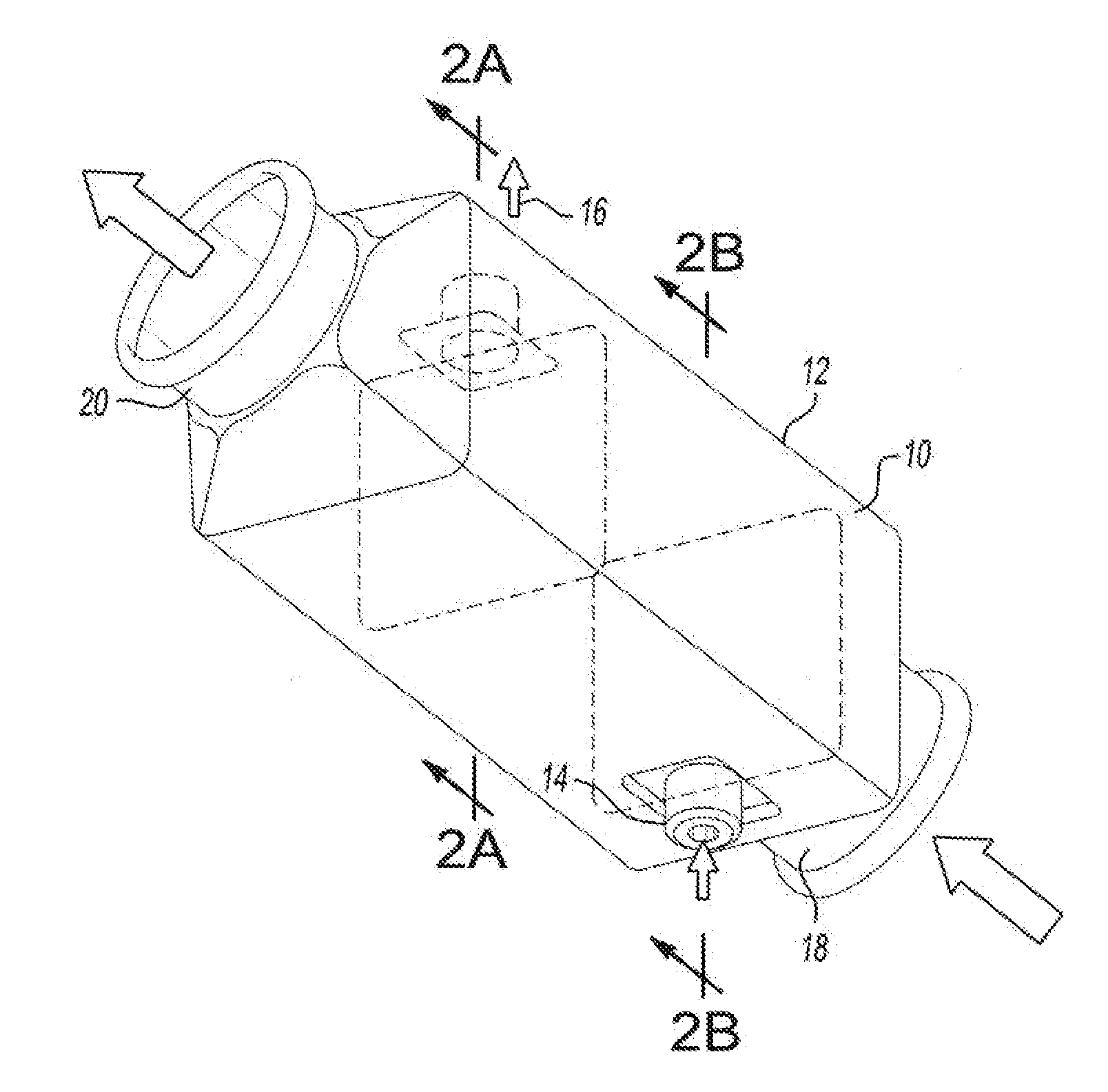
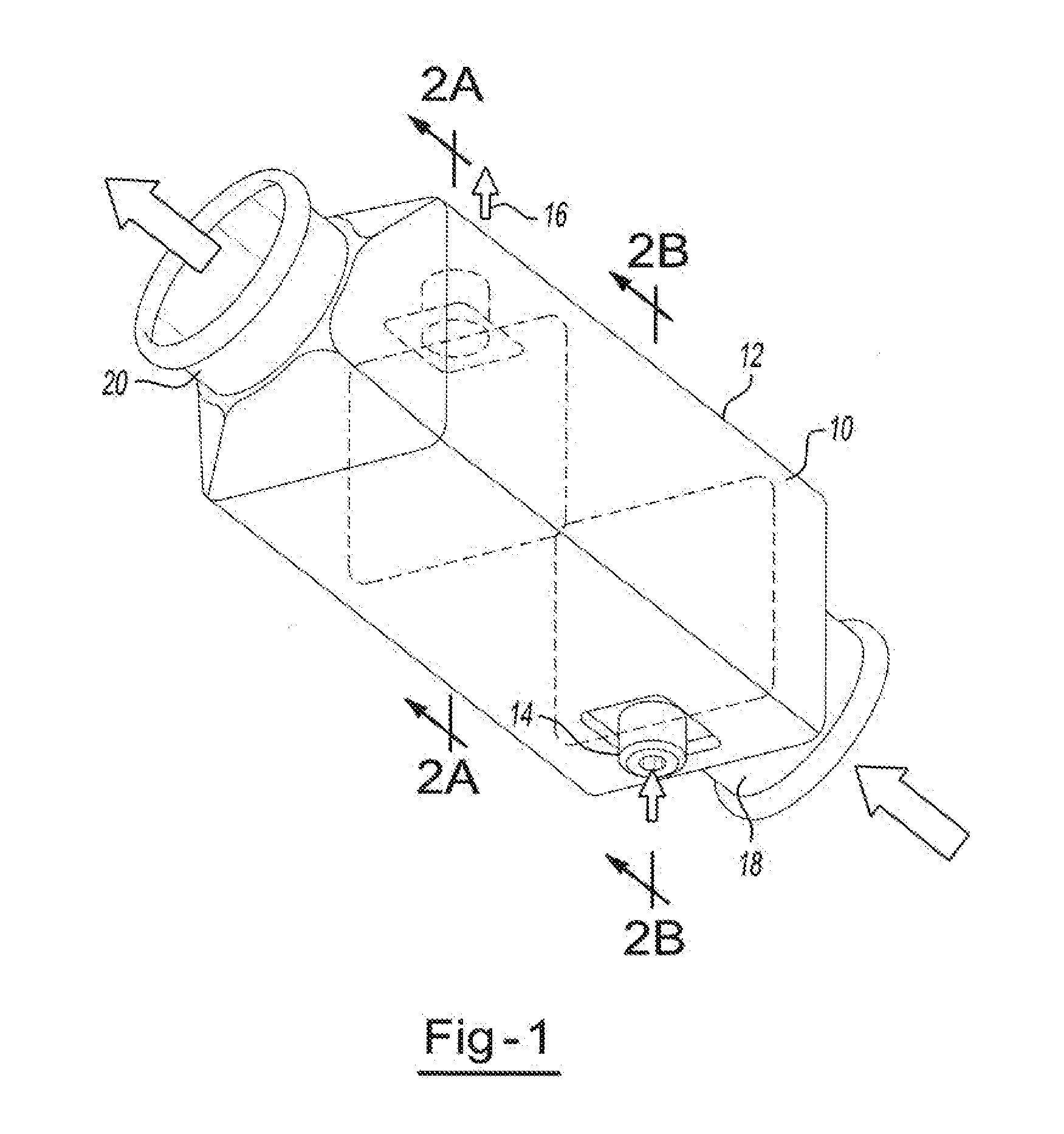
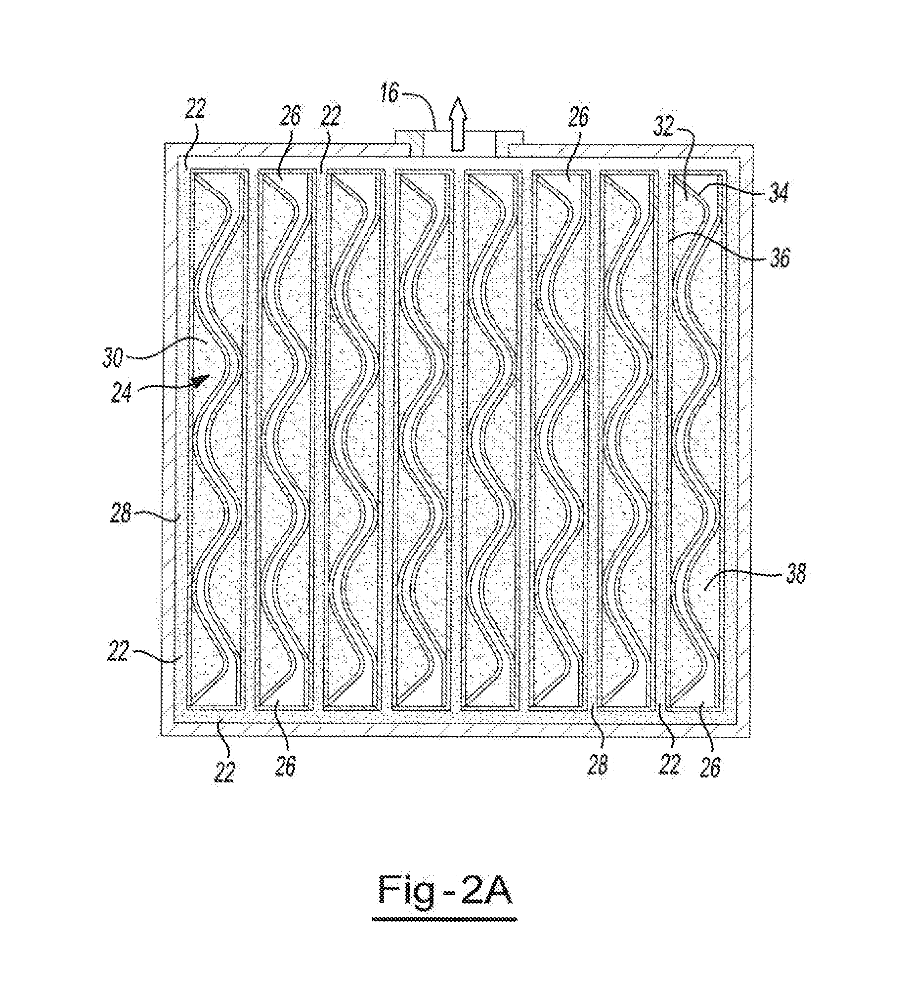
[0020]As will be seen from the teachings herein, the present invention provides a unique and unexpectedly efficient approach to the packaging and containment of thermal energy storage materials (which also includes what is commonly called “phase change materials”) for heat storage and discharge applications, and particularly for applications requiring high power de...


PUM


Abstract

An enhanced heat transfer between stored thermal energy and a heat recipient via a capillary pumped loop. The devices, systems and methods employ a thermal energy storage material having a solid to liquid phase transition at a temperature and a structure having a plurality of capillaries.

Description

CLAIM OF PRIORITY[0001]The present application claims the benefit of the filing date of US Provisional Patent Application No.: 61 / 245,767 (filed on Sep. 25, 2009 by Soukhojak et al.), the contents of which is incorporated herein by reference in its entirety.FIELD OF THE INVENTION[0002]The present invention relates to enhanced heat transfer between stored thermal energy and a heat recipient via a capillary pumped loop.BACKGROUND OF THE INVENTION[0003]Industry in general has been actively seeking a novel approach to capture and store waste heat efficiently such that it can be utilized at a more opportune time. Further, the desire to achieve energy storage in a compact space demands the development of novel materials that are capable of storing high energy content per unit weight and unit volume. Areas of potential application of breakthrough technology include transportation, solar energy, industrial manufacturing processes as well as municipal and / or commercial building heating.[0004...

Claims


Application Information

Patent Timeline
Patent Type & Authority Applications(United States)
IPC IPC(8): F28D20/00F28D15/04F01N5/02F28D15/02
CPCF28D15/043Y02E60/145F28D20/028F28D20/023Y02E60/14
Inventor SOUKHOJAK, ANDREY N.BANK, DAVID H.
Owner DOW GLOBAL TECH LLC
Why Eureka
Try Eureka