
Anti-fouling spark plug and method of making

Active Publication Date: 2012-07-05
FRAM GROUP IP +1
View PDF3 Cites 5 Cited by
  • Summary
  • Abstract
  • Description
  • Claims
  • Application Information

AI Technical Summary

Benefits of technology

[0007]Also disclosed herein are methods of making the coated insulative sleeve and a spark plug comprising the coated insulative sleeve.

Problems solved by technology

A significant build up of combustion products may foul the spark plug and resulting in ignition failure, i.e., the combustion products completely block the spark from forming between the center and ground electrodes.
Combustion deposit build up is particularly problematic during cold starts.
During cold starts, complete combustion of the air / fuel mixture is seldom achieved which results in an increased generation of electrically conductive combustion deposits.
As a result of continuous cold starts, electrically conductive combustion deposits build up resulting in an electrical short circuit between the center electrode and the electrically grounded portion of the spark plug.
These coatings have failed to adequately address the issue, suffering from inadequate performance at elevated temperature, inadequate endurance, or insufficient reduction of combustion deposit build up.

Method used


Image

  • Anti-fouling spark plug and method of making
  • Anti-fouling spark plug and method of making
  • Anti-fouling spark plug and method of making

Examples


Embodiment Construction

[0010]The coating comprising a silicone resin, as described herein, is a substantially continuous coating. A substantially continuous coating, as defined herein, describes a coating which is has no breaks or gaps visible to the naked eye and covers the exterior surface of the insulative sleeve. The coating thickness can be 1 to 20 micrometers in thickness, or, more specifically 1 to 15 micrometers in thickness.

[0011]Silicone resins are highly branched, three dimensional framework polymers that are cross-linked. They can comprise randomly ordered, mainly trifunctional units. Silicone resins can range from being relatively low molecular weight reactive resins to high molecular weight materials with very diverse structures. Silicone resins differ from silicone fluids (oils) in that silicone fluids are linear, non-cross-linked polymers that typically comprise dimethylsiloxane units.

[0012]The silicone resin can have a decomposition temperature greater than or equal to 500° C., or, more s...


PUM


Abstract

Disclosed herein is a spark plug comprising an insulative sleeve having a central axial bore and an exterior surface and a center electrode extending through the central axial bore of the insulative sleeve. The insulating sleeve is positioned within, and secured to, a metal shell that serves as a mounting platform and interface to an internal combustion engine. The metal sleeve also supports a ground electrode that is positioned in a spaced relationship relative to the center electrode so as to generate a spark gap. The insulating sleeve includes a shaped tip portion that resides in a recessed end portion of the metal shell. A coating is disposed on the exterior surface of the insulative sleeve. The coating comprises a silicone resin, optionally in combination with a filler.

Description

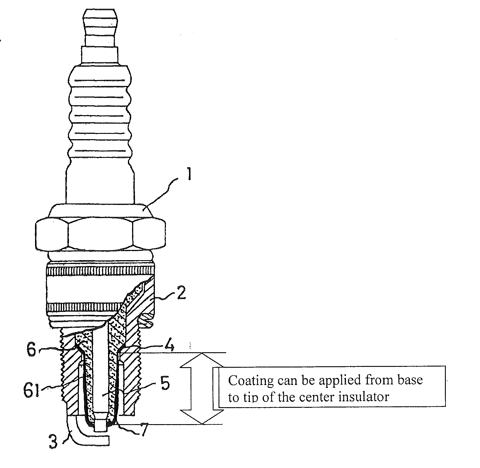
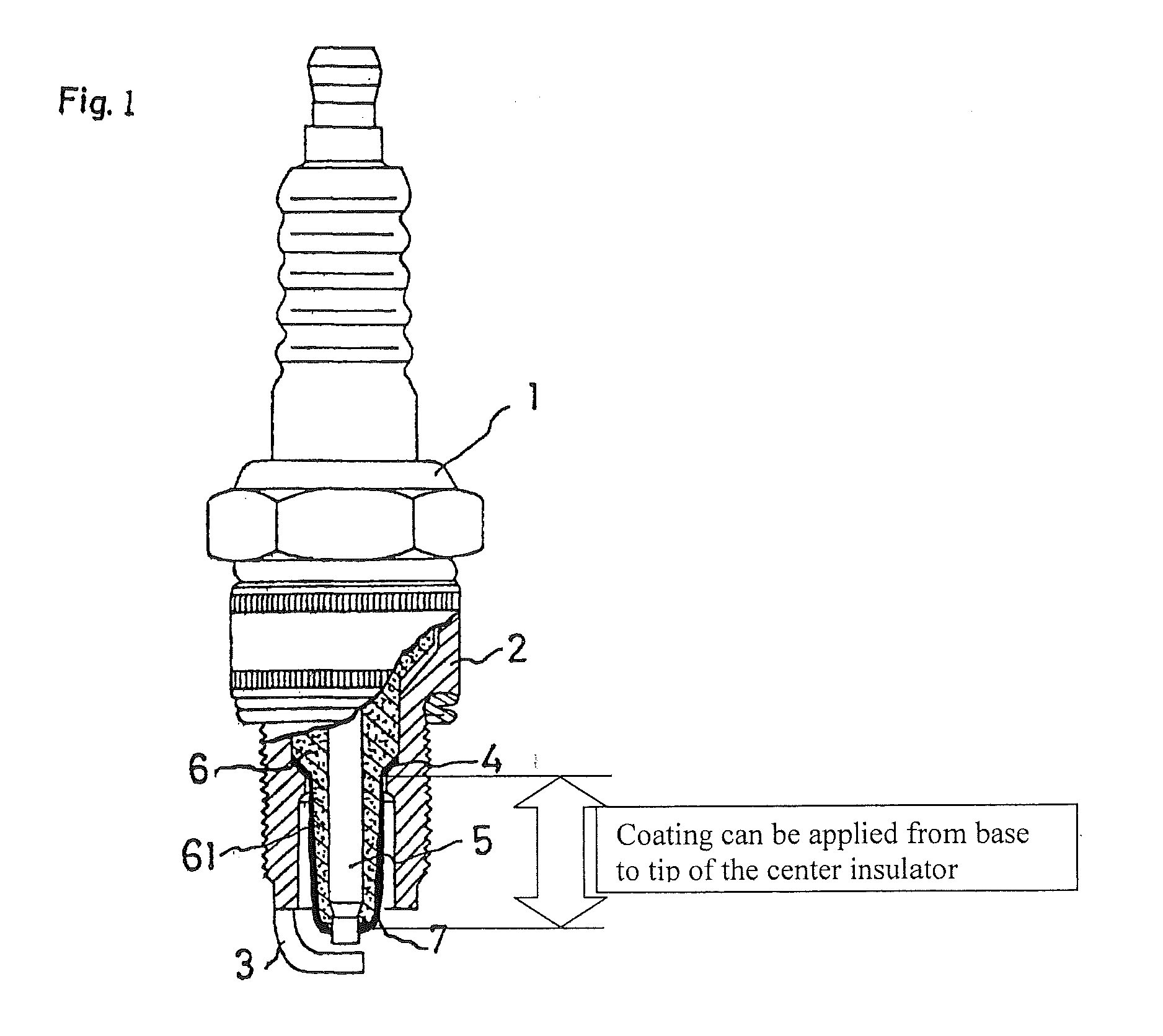
CROSS REFERENCE TO RELATED APPLICATIONS[0001]This application claims the benefit of U.S. Provisional Patent Application No. 61 / 420,127 filed on Dec. 6, 2010, which is incorporated by reference herein in its entirety.BACKGROUND[0002]In general, spark plugs include an insulative sleeve having a central axial bore through which a center electrode extends. The insulating sleeve is positioned within, and secured to, a metal shell that serves as a mounting platform and interface to an internal combustion engine. The metal sleeve also supports a ground electrode that is positioned in a particular spaced relationship relative to the center electrode so as to generate a spark gap. The insulating sleeve includes a shaped tip portion that resides in a recessed end portion of the metal shell. The shaped tip portion is configured to protect the electrode from engine heat and products of combustion. The spark plug is typically mounted to an engine cylinder head and selectively activated to ignite...

Claims


Application Information

Patent Timeline
IPC IPC(8): H01T13/02B05D3/02B05D5/12
CPCH01T13/14H01T21/02H01T13/20
Inventor UNGER, PETERROHRBACH, RONBOEHLER, JEFFZHENG, JING
Owner FRAM GROUP IP
Learn More