
Methods, systems and apparatus for adjusting duty cycle of pulse width modulated (PWM) waveforms

a technology of pulse width and duty cycle, applied in the direction of dynamo-electric converter control, motor/generator/converter stopper, dynamo-electric gear control, etc., can solve the problems of current/torque oscillation and inapplicability of transition angl

Active Publication Date: 2012-07-05
GM GLOBAL TECH OPERATIONS LLC
View PDF1 Cites 40 Cited by
  • Summary
  • Abstract
  • Description
  • Claims
  • Application Information

AI Technical Summary

Benefits of technology

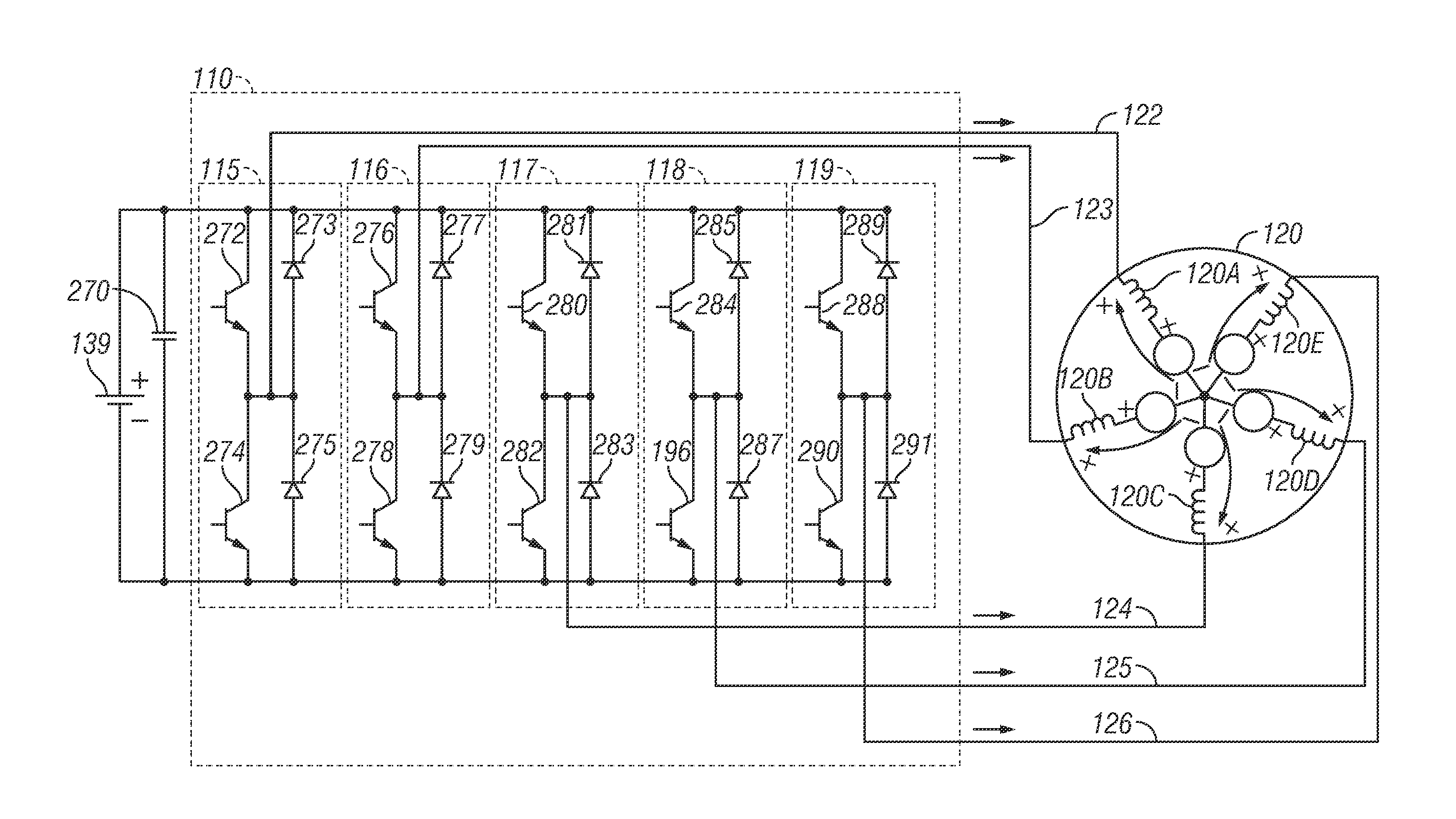
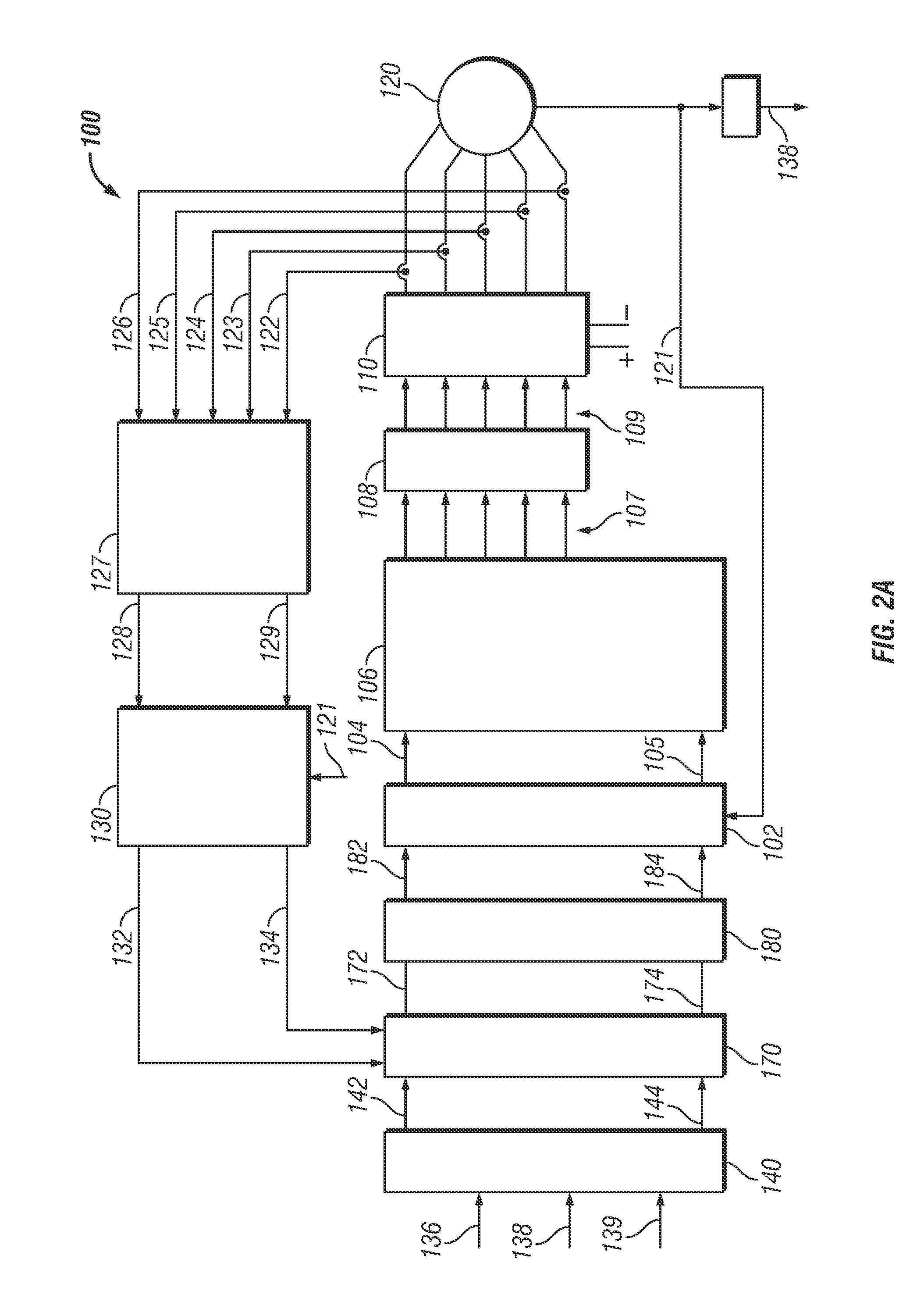
[0013]Embodiments of the present invention relate to methods, systems and apparatus for controlling operation of a multi-phase machine in a vector controlled motor drive system that includes a multi-phase PWM controlled inverter module that drives the multi-phase machine when the multi-phase machine operates in an overmodulation region. The disclosed embodiments provide a mechanism for adjusting a duty cycle of PWM waveforms so that the correct phase voltage command signals are applied to the multi-phase machine. This can reduce variations / errors in the phase voltage command signals that are applied to the multi-phase machine so that phase current may be properly regulated thus reducing current / torque oscillation, which can in turn improve machine efficiency and performance, as well as utilization of the DC voltage source.

Problems solved by technology

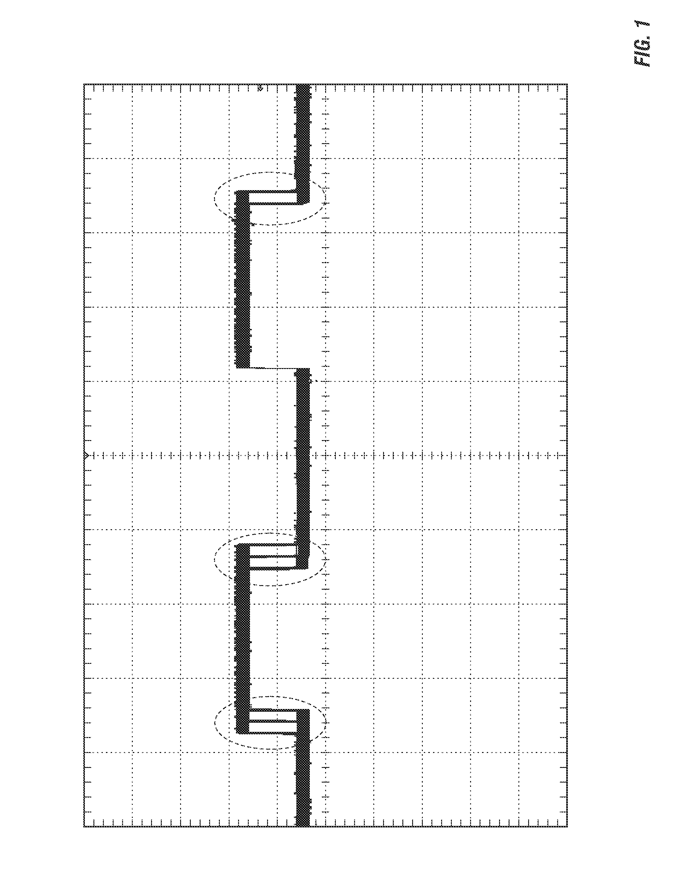
Although the PWM module can update / adjust the duty cycle of the PWM waveforms each time it encounters the end “boundary angle” of a current PWM period, this duty cycle is only valid with respect to transition angles that occur before it was calculated, and is not valid for transition angles that occur afterwards.
As a result, the wrong phase voltage will be applied to the machine, and therefore, phase current may not be properly regulated, which may in turn cause current / torque oscillations.

Method used


Image

  • Methods, systems and apparatus for adjusting duty cycle of pulse width modulated (PWM) waveforms
  • Methods, systems and apparatus for adjusting duty cycle of pulse width modulated (PWM) waveforms
  • Methods, systems and apparatus for adjusting duty cycle of pulse width modulated (PWM) waveforms

Examples


Embodiment Construction

[0028]As used herein, the word “exemplary” means “serving as an example, instance, or illustration.” The following detailed description is merely exemplary in nature and is not intended to limit the invention or the application and uses of the invention. Any embodiment described herein as “exemplary” is not necessarily to be construed as preferred or advantageous over other embodiments. All of the embodiments described in this Detailed Description are exemplary embodiments provided to enable persons skilled in the art to make or use the invention and not to limit the scope of the invention which is defined by the claims. Furthermore, there is no intention to be bound by any expressed or implied theory presented in the preceding technical field, background, brief summary or the following detailed description.

[0029]Before describing in detail embodiments that are in accordance with the present invention, it should be observed that the embodiments reside primarily in combinations of me...


PUM


Abstract

Embodiments of the present invention relate to methods, systems and apparatus for controlling operation of a multi-phase machine in a vector controlled motor drive system when the multi-phase machine operates in an overmodulation region. The disclosed embodiments provide a mechanism for adjusting a duty cycle of PWM waveforms so that the correct phase voltage command signals are applied at the angle transitions. This can reduce variations / errors in the phase voltage command signals applied to the multi-phase machine so that phase current may be properly regulated thus reducing current / torque oscillation, which can in turn improve machine efficiency and performance, as well as utilization of the DC voltage source.

Description

STATEMENT REGARDING FEDERALLY SPONSORED RESEARCH OR DEVELOPMENT[0001]This invention was made with Government support under DE-FC26-07NT43123, awarded by the US-Department of Energy. The Government has certain rights in this invention.TECHNICAL FIELD[0002]Embodiments of the present invention generally relate to techniques for controlling operation of multi-phase systems, and more particularly relate to methods, systems and apparatus for adjusting duty cycle of pulse width modulated (PWM) waveforms used to control a multi-phase machine.BACKGROUND OF THE INVENTION[0003]Electric machines are utilized in a wide variety of applications. For example, hybrid / electric vehicles (HEVs) typically include an electric traction drive system that includes an alternating current (AC) electric motor which is driven by a power converter with a direct current (DC) power source, such as a storage battery. Motor windings of the AC electric motor can be coupled to inverter sub-modules of a power inverter ...

Claims


Application Information

Patent Timeline
Patent Type & Authority Applications(United States)
IPC IPC(8): H02P6/00
CPCH02P25/22H02P21/12H02P27/08
Inventor GALLEGOS-LOPEZ, GABRIELKINOSHITA, MICHAEL H.RANSOM, RAY M.PERISIC, MILUN
Owner GM GLOBAL TECH OPERATIONS LLC
Learn More