Duty cycle corrector and duty cycle correction method

Active Publication Date: 2012-07-05
NXP USA INC
View PDF7 Cites 15 Cited by
  • Summary
  • Abstract
  • Description
  • Claims
  • Application Information

AI Technical Summary

Problems solved by technology

An available clock signal does not necessarily have the desired duty cycle.
This can be problematic in a synchronous di

Method used


Image

  • Duty cycle corrector and duty cycle correction method
  • Duty cycle corrector and duty cycle correction method
  • Duty cycle corrector and duty cycle correction method

Examples


Embodiment Construction

[0028]Because the apparatus implementing the present invention is, for the most part, composed of electronic components and circuits known to those skilled in the art, circuit details will not be explained in any greater extent than that considered necessary for the understanding and appreciation of the underlying concepts of the present invention and in order not to obfuscate or distract from the teachings of the present invention.

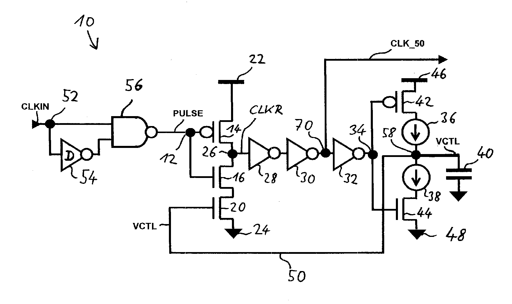
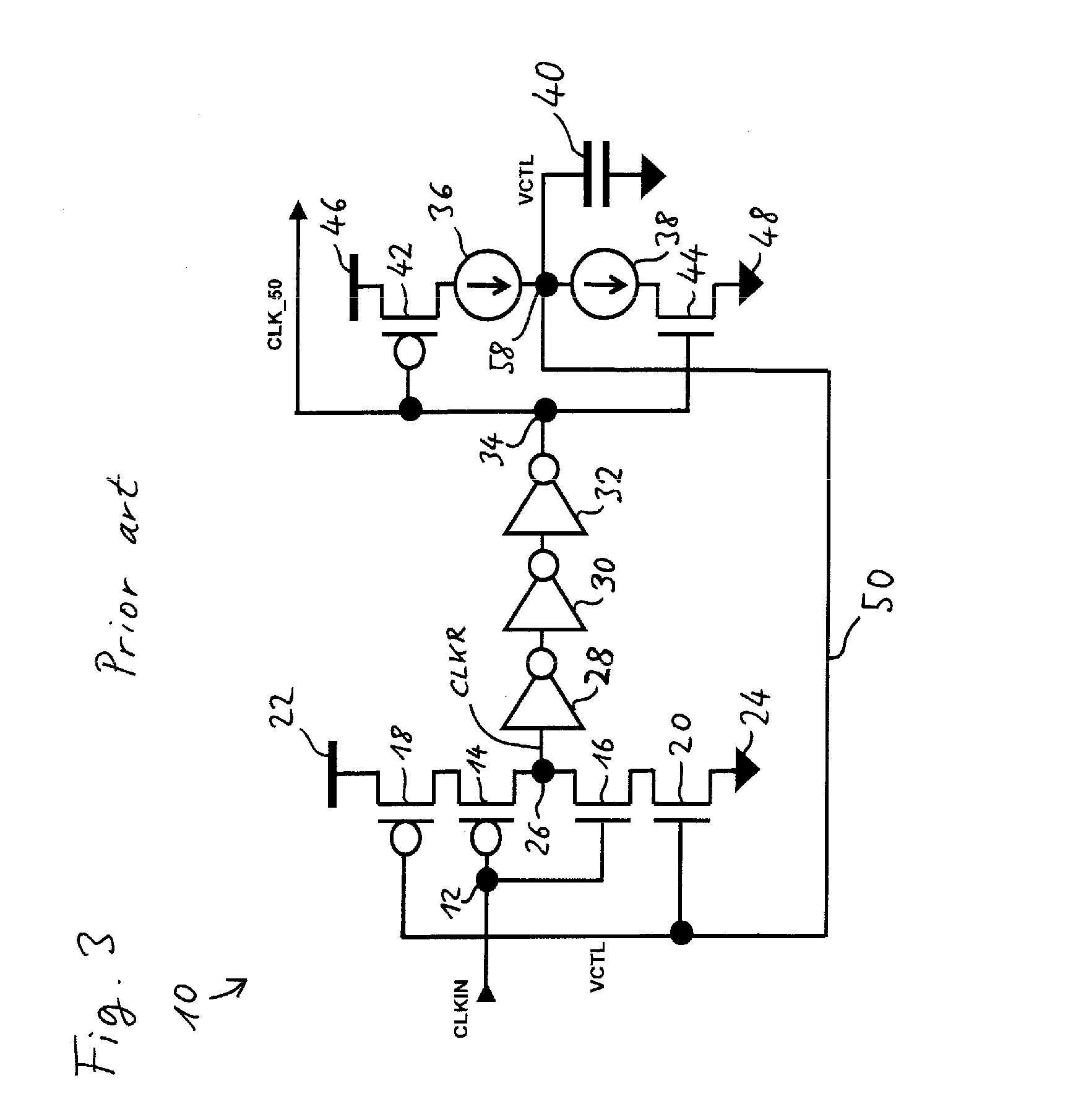
[0029]Shown in FIG. 5 is an example of a synchronous digital system 60 comprising, by way of example, a processing unit 62 and a memory 64 operably coupled to each other. A raw clock signal RAW_CLK is fed to the processing unit 62 and to the memory 64 via a clock tree comprising nodes 52, 66, and 68, to provide the processing unit 62 and the memory 64 with clock signals CLK and CLK_50, respectively. The clock branch to the memory 64 comprises a duty cycle corrector 10 that will be described below with reference to FIGS. 7 to 11.

[0030]The clock signals CLK...


PUM


Abstract

The invention relates to a duty cycle corrector for generating from an input clock signal an output clock signal having a desired duty cycle. The duty cycle corrector comprises a pulse generating stage for generating from the input clock signal a pulsed clock signal. The pulse generating stage converts rising edges of the input clock signal into pulses, each of which pulses is shorter than the desired duty cycle times the clock period. The duty cycle corrector further comprises a pulse stretching stage for generating from the pulsed clock signal the output clock signal, the pulse stretching stage delaying falling edges of the pulsed clock signal by a controlled delay. The duty cycle corrector may comprise a duty cycle detector for generating a control signal as a function of the duty cycle of the output clock signal, and a feedback path for delivering the control signal to the pulse stretching stage so as to increase the controlled delay when the duty cycle is less than the desired duty cycle and to decrease the controlled delay when the duty cycle is greater than the desired duty cycle. The invention also relates to a method of generating from an input clock signal an output clock signal having a desired duty cycle.

Description

FIELD OF THE INVENTION[0001]This invention relates to a duty cycle corrector for generating from an input clock signal an output clock signal having a desired duty cycle.[0002]The invention also relates to a synchronous circuit comprising such a duty cycle corrector.[0003]The invention further relates to a method of generating from an input clock signal an output clock signal having a desired duty cycle.BACKGROUND OF THE INVENTION[0004]In a synchronous digital system, different components of the system are synchronized by means of a clock signal. A clock signal is a succession of high and low values. Typically, the high values are provided by a high voltage level while the low values are provided by a low voltage level. The clock signal is typically periodic, both for the sake of simplicity and to maximize the number of operations per second performed by the synchronous circuit. The clock signal can take the form of a square wave, a sinusoidal wave, a succession of pulses, or any ot...

Claims


Application Information

Patent Timeline
IPC IPC(8): H03K5/04H03K3/017
CPCH03K5/1565
Inventor SOFER, SERGEYMELAMED-KOHEN, EYALNEIMAN, VALERY
Owner NXP USA INC
Why Eureka
Try Eureka