This helps you quickly interpret patents by identifying the three key elements:
Problems solved by technology
Method used
Benefits of technology
Benefits of technology
[0012]It is particularly favorable when the at least one amplifier module behaves in an optically neutral manner with respect to the resonator modes so that the amplifier module forms a unit which can preferably be arranged in the amplifying unit, i.e. many times in the amplifying unit, in a scalable manner.
[0065]In this respect, it is favorable, in particular, when the intermediate imaging branch is designed to be optically neutral.
Problems solved by technology
Laser amplifier systems of this type are conventional laser amplifier systems, wherein the problem with the configuration of the laser amplifier systems is that the optical behavior of the laser-active medium has to be taken into consideration for the configuration of the resonator and, therefore, the resonator radiation field which results is always dependent on the optical behavior of the laser-active medium.
Method used
Image
Click on the blue label to locate the original text in one second.
Reading with bidirectional positioning of images and text.
Examples
first embodiment
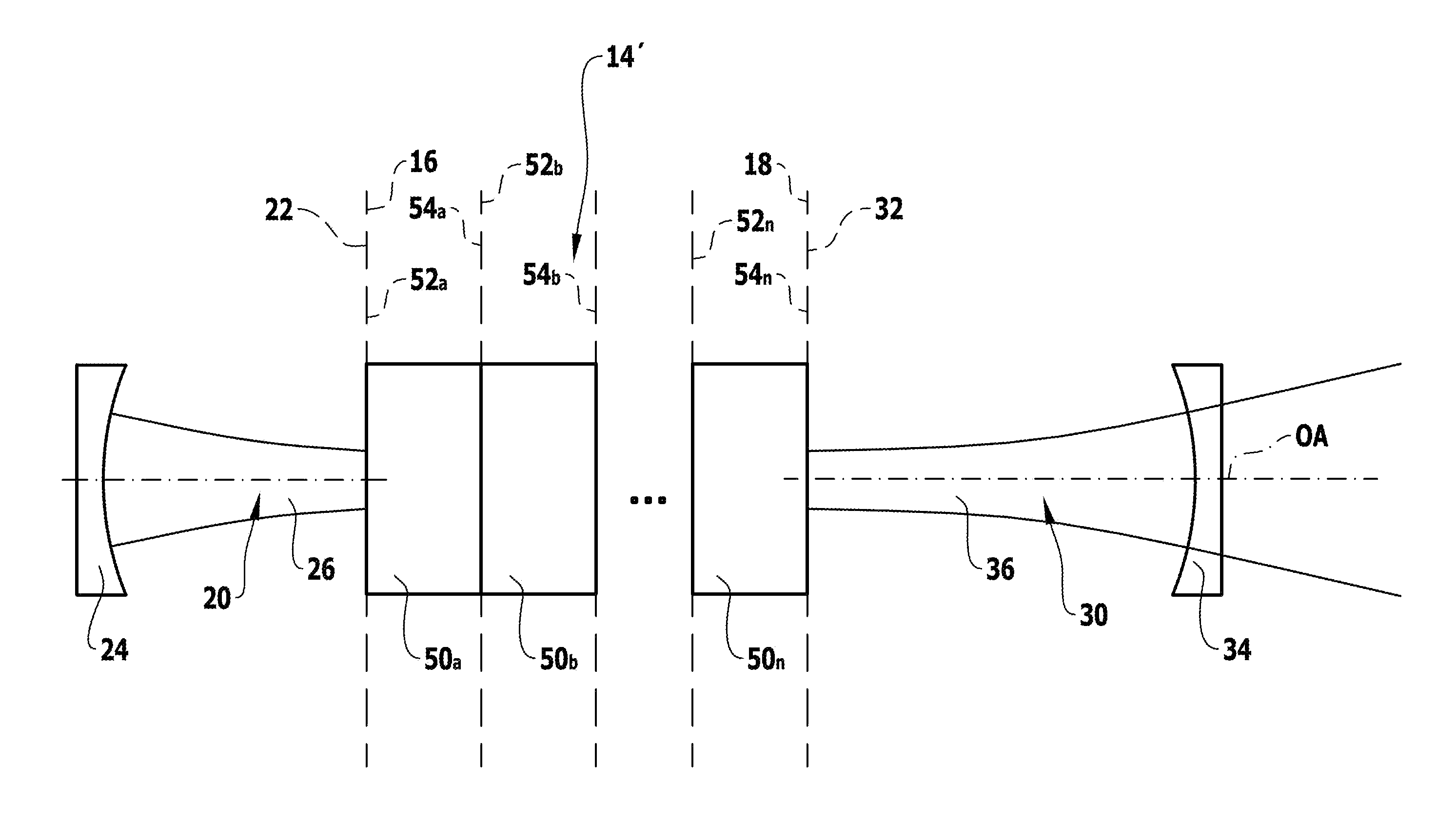
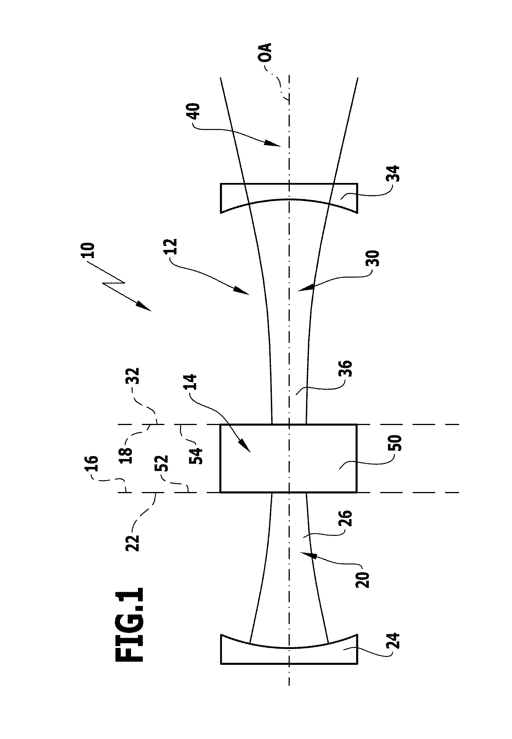
[0100]A first embodiment, illustrated in FIG. 1, of a laser amplifier system 10 according to the invention, which is arranged along an optical axis OA, comprises a resonator 12 and an amplifier unit 14 which is designed to be optically independent of the resonator 12 and borders on resonator sections of the resonator, which is designed to be split, in a direct optical manner with end planes 16 and 18.
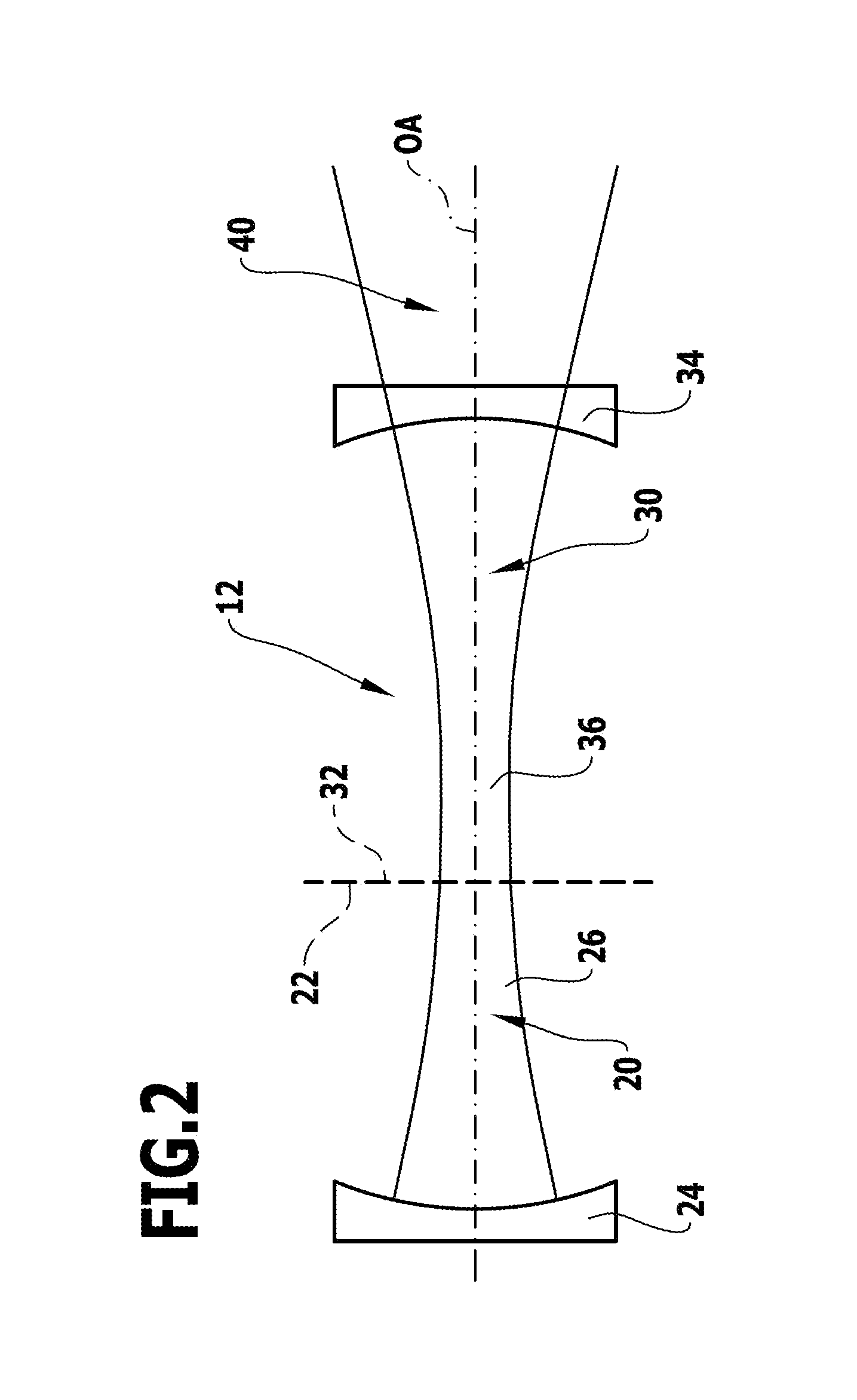
[0101]A resonator 12 designed to be split is to be understood in that resonator sections 20, 30 extend from two respective virtual planes of separation 22 and 32, wherein the virtual planes of separation 22 and 32 coincide with the end planes 16 and 18 of the amplifier unit and wherein the resonator sections 20, 30 have an optical layout which assumes that the amplifier unit 14 does not exist optically and the virtual planes of separation 22 and 32 coincide, as illustrated in FIG. 2, so that the optical behavior of the amplifier unit 14 is not mode-relevant for the optical layout of the...
second embodiment
[0123]In an amplifier module 50′ according to the invention, illustrated in FIG. 9, the optically amplifying laser-active medium LM is integrated into the imaging elements 56′, 58′ so that the additional small solid-state plate members 62, 64 as carriers for the laser-active medium LM can be omitted. In this case, the effects of the solid-state plate members on the optical system 80′ are not applicable and so this can be dimensioned more easily.
[0124]In the first and second embodiments of the optical system 80 and 80′ according to the invention, the arrangement of the laser-active medium LM is independent of its position in the amplifier module radiation field 60; it has merely to be taken into account for the arrangement of the laser-active medium LM that the respective pumping light spot 72, 74 is adapted to the amplifier module radiation field cross section 76, 78 in order to pump the laser-active medium LM efficiently, where applicable in adaptation to the selected resonator mod...
fourth embodiment
[0130]In an amplifier module 50′″ according to the invention, illustrated in FIG. 11, the optical system 80′″ is dimensioned as a whole in the same way as described above and so this has the same transformation behavior between the module end planes 52, 54 as the preceding amplifier modules.
[0131]The radiation field pieces 53 and 55 adjoin the amplifier module 50′″ on both sides and these are either pieces of resonator radiation field sections 26 and 36, respectively, which adjoin the module plane 52, 54 or of amplifier modules 50 which are adjacent to amplifier module radiation fields 60 or of radiation fields of additional, intermediate imaging systems.
[0132]In contrast to the preceding amplifier modules, the optical system 80′″ does, however, comprise altogether two planes of imaging 82 and 84, in which the small solid-state plate members 62, 64 are, for example, arranged, between the module end planes 52, 54.
[0133]Furthermore, the optical system 80′″ likewise comprises the two a...
PUM
Abstract
A laseramplifiersystem is provided which comprises a resonator with optical resonator elements which determine a course of a resonatorradiation field which propagates along an optical axis and at least one laser-active medium (LM). The resonator is designed as a split resonator and has a first resonator section which extends from a first virtual plane of separation and a second resonator section which extends from a second virtual plane of separation. The resonator sections are dimensioned optically such that the resonator radiation field has radiation field states corresponding to the same resonator modes in each of the virtual planes of separation. An amplifying unit optically independent of the resonator is arranged between the first and the second virtual planes of separation. The amplifying unit comprises the at least one laser-active medium and couples the radiation field states in a neutral manner with respect to the resonator modes.
Description
[0001]This application is a continuation of International application number PCT / EP2010 / 055755 filed on Apr. 28, 2010.[0002]This patent application claims the benefit of International application No. PCT / EP2010 / 055755 of Apr. 28, 2010 and German application No. 10 2009 020 768.6 of Apr. 30, 2009, the teachings and disclosure of which are hereby incorporated in their entirety by reference thereto.BACKGROUND OF THE INVENTION[0003]The invention relates to a laser amplifiersystem, comprising a resonator with optical resonator elements which determine a course of a resonator radiation field which propagates along an optical axis and at least one laser-active medium.[0004]Laseramplifier systems of this type are conventional laser amplifier systems, wherein the problem with the configuration of the laser amplifier systems is that the optical behavior of the laser-active medium has to be taken into consideration for the configuration of the resonator and, therefore, the resonator radiatio...
Claims
Application Information
Patent Timeline
Application Date:The date an application was filed.
Publication Date:The date a patent or application was officially published.
First Publication Date:The earliest publication date of a patent with the same application number.
Issue Date:Publication date of the patent grant document.
PCT Entry Date:The Entry date of PCT National Phase.
Estimated Expiry Date:The statutory expiry date of a patent right according to the Patent Law, and it is the longest term of protection that the patent right can achieve without the termination of the patent right due to other reasons(Term extension factor has been taken into account ).
Invalid Date:Actual expiry date is based on effective date or publication date of legal transaction data of invalid patent.

