Process and device for deploying an Anti-scattering grid

a grid and anti-scattering technology, applied in the field of medical imaging, can solve the problems of deteriorating the quality and legibility of the frame obtained, the image of the grid appearing on the detector,

Active Publication Date: 2012-07-05
GENERAL ELECTRIC CO
View PDF5 Cites 18 Cited by
  • Summary
  • Abstract
  • Description
  • Claims
  • Application Information

AI Technical Summary

Benefits of technology

[0020]Embodiments of the present invention provide a process and device for deploying an anti-scattering grid, applicable to m...

Problems solved by technology

One drawback of using such a grid is that an image of the grid appears on the detector.
Also, alternating laminates can ...

Method used


Image

  • Process and device for deploying an Anti-scattering grid
  • Process and device for deploying an Anti-scattering grid
  • Process and device for deploying an Anti-scattering grid

Examples


Embodiment Construction

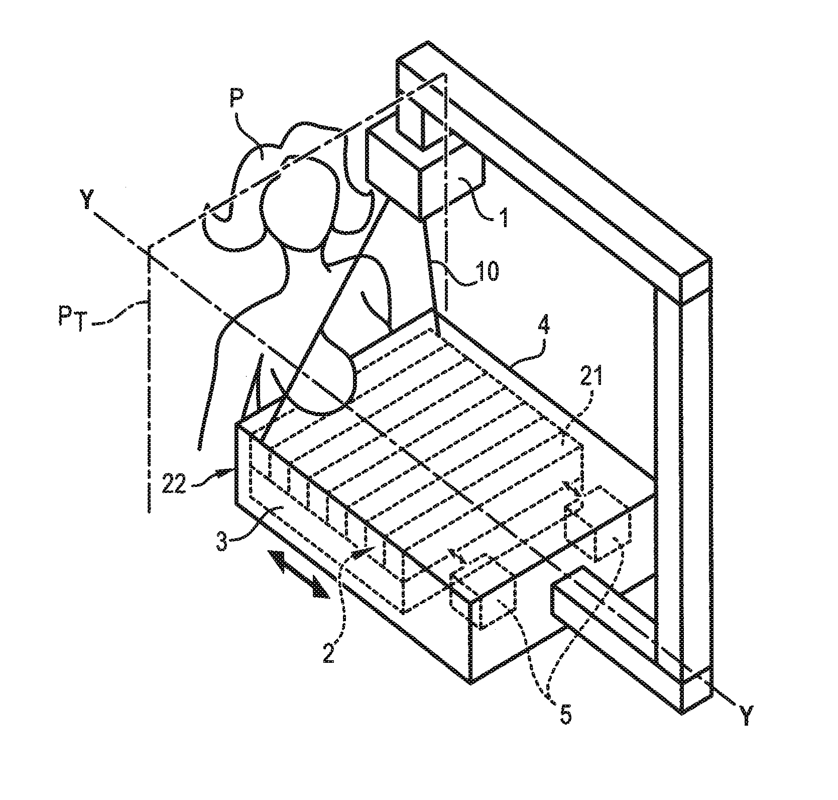
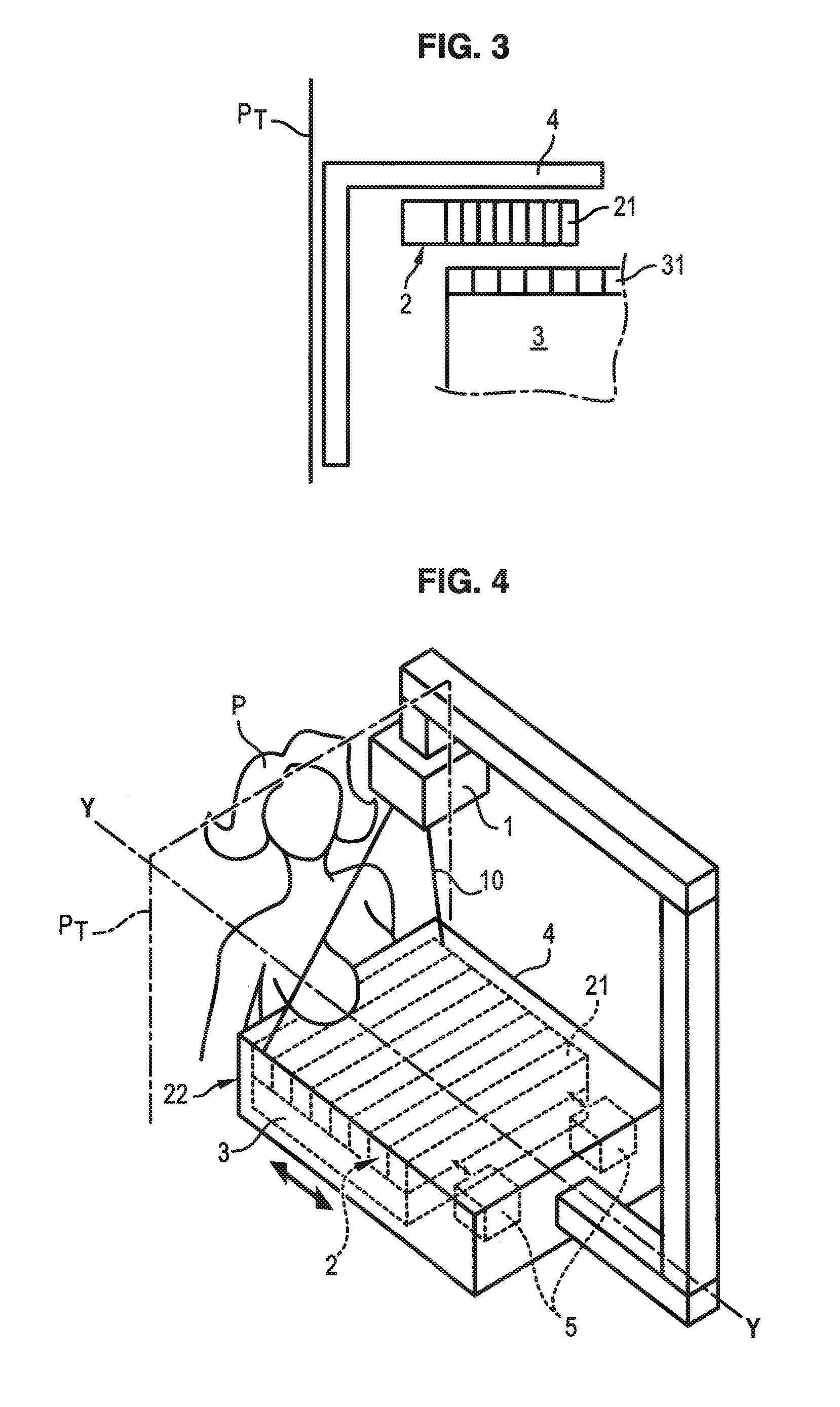
[0032]In reference to FIG. 4, a mammograph is illustrated comprising a radiation source 1, for example of X-ray type, emitting radiation 10 designed to illuminate the breast of a patient P of whom images are to be taken during a pause time T. The radiations transmitted then reach a detector 3 made up of a network of sensors 31 distributed periodically with a pitch pd of the detector, of the order of 100 to 200 μm.

[0033]An anti-scattering grid 2 is interposed between the source 1 and the detector 3, more precisely between the breast of the patient P and the detector 3, so as to stop radiations scattered by the breast of the patient P not coming directly from the source 1.

[0034]This anti-scattering grid 2 is placed immediately above the detector 3, and is held by means of a cap 4. This cap also forms the support of the breast of the patient to be examined.

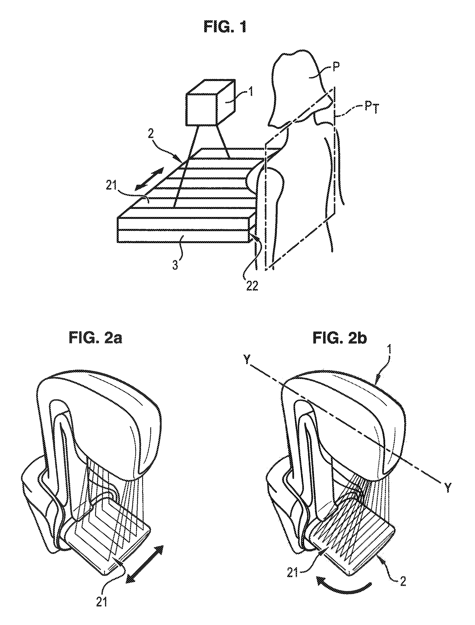
[0035]The grid 2 comprises alternating radio-opaque laminates 21, for example constituted by metal, and radio-transparent laminates...


PUM

PropertyMeasurementUnit
Speedaaaaaaaaaa
Frequencyaaaaaaaaaa
Displacementaaaaaaaaaa

Abstract

A process for deploying an anti-scattering grid in a mammograph is provided. The mammograph comprises a radiation source configured to emit radiation for taking mammographic images of a patient, a radiation detector comprising a network of sensors arranged periodically with a first pitch, and an anti-scattering grid arranged between the source and the detector, the anti-scattering grid comprising absorption laminates of radiations arranged parallel to each other and distributed periodically with a second pitch. The process comprises: displacing the anti-scattering grid relative to the detector or displacing the detector relative to the anti-scattering grid during emission of radiation; and adapting the second pitch to the first pitch, wherein displacement is perpendicular to the direction of the laminates of the anti-scattering grid, the laminates being arranged parallel to a side of the anti-scattering grid positioned against the patient.

Description

BACKGROUND OF THE INVENTION[0001]1. Field of the Invention[0002]The present disclosure is generally related to the field of medical imaging, and more particularly the field of radiography. Embodiments of the present invention relate to the field of the deploying anti-scattering grids used to improve radiographic frames by filtering the photons scattered by the organ under study, and keeping only the photons emitted by the source. Embodiments of the present invention can be utilised within the scope of mammography, and more particularly within the scope of mammary tomosynthesis, which takes a series of frames at different angles to produce a 3D image of the object being studied.[0003]2. Description of the Prior Art[0004]Anti-scattering grids are used widely in radiography devices to eliminate effects due to parasite scattering of some photons, taking place in the organ studied in said devices. These grids filter photons scattered by the organ being studied and mainly keep only photon...

Claims


Application Information

Patent Timeline
IPC IPC(8): A61B6/00B23P11/00
CPCA61B6/06Y10T29/49826A61B6/4291A61B6/502
Inventor SOUCHAY, HENRICISARUK, MATHIAS
Owner GENERAL ELECTRIC CO
Why Eureka
Try Eureka