
Intercellular separation structure body and laminate type solid secondary battery provided with the same

a technology of intercellular separation and which is applied in the direction of secondary cell details, sustainable manufacturing/processing, and flat cell grouping. it can solve the problems of increasing the amount of use of electroconductive materials, deteriorating the battery characteristics of laminate type solid secondary batteries, and reducing the number of external current-collecting members. , excellent space utilization ratio and cost performan

Active Publication Date: 2012-07-05
MURATA MFG CO LTD
View PDF5 Cites 4 Cited by
  • Summary
  • Abstract
  • Description
  • Claims
  • Application Information

AI Technical Summary

Benefits of technology

[0009]On the other hand, in the other laminate type solid secondary battery disclosed in Patent Document 1, the unit cells are electroconductively and ion-conductively insulated from each other by the insulating layer, and the unit cells are connected electrically in series and / or in parallel by the leading tabs disposed on the outside of the unit cells. Since the insulating layer is used in order to insulate the unit cells electroconductively and ion-conductively from each other, the positive electrode layer and the negative electrode layer are not ion-conductively conducted via the current-collecting layer even when the current-collecting layer substantially has an ion-conductive property. This can prevent the battery characteristics of the laminate type solid secondary battery from being deteriorated.
[0032]As described above, according to this invention, the unit cells constituting a laminate type solid secondary battery can be electrically connected while reducing the number of external current-collecting members such as leading tabs as much as possible, and also the positive electrode layer and the negative electrode layer can be ion-conductively insulated from each other efficiently irrespective of the presence or absence of a current-collecting layer, so that an intercellular separation structure body being excellent in space utilization ratio and cost performance can be imparted to the laminate type solid secondary battery.

Problems solved by technology

However, in this laminate type solid secondary battery, when the positive electrode layer and the negative electrode layer are ion-conducted via the current-collecting layer, only the ion-conducted positive electrode layer and negative electrode layer are discharged, thereby considerably deteriorating the battery characteristics of the laminate type solid secondary battery.
In the former case, it will be difficult to apply a technique such as the sputtering method or the screen printing of an electroconductive material that is generally used as a method of forming the current-collecting layer.
In the latter case, there is a problem of an increase in the amount of use of the electroconductive material (metal paste or the like) constituting the current-collecting layer.

Method used


Image

  • Intercellular separation structure body and laminate type solid secondary battery provided with the same
  • Intercellular separation structure body and laminate type solid secondary battery provided with the same
  • Intercellular separation structure body and laminate type solid secondary battery provided with the same

Examples


first embodiment

[0046]First, a laminate body constituting a first basic structure of a laminate type solid secondary battery as the first embodiment of this invention will be described. Here, in each of the later described embodiments of the present invention, the planar shape of the laminate body is not limited; however, description will be given by assuming that the shape is generally rectangular, for example.

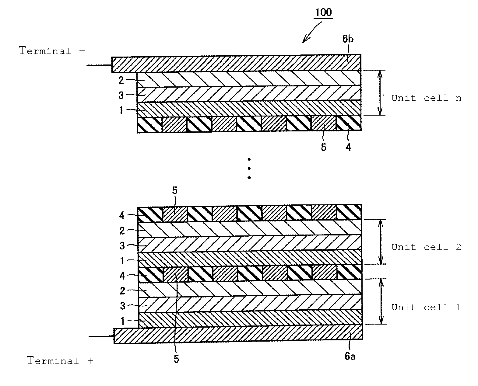
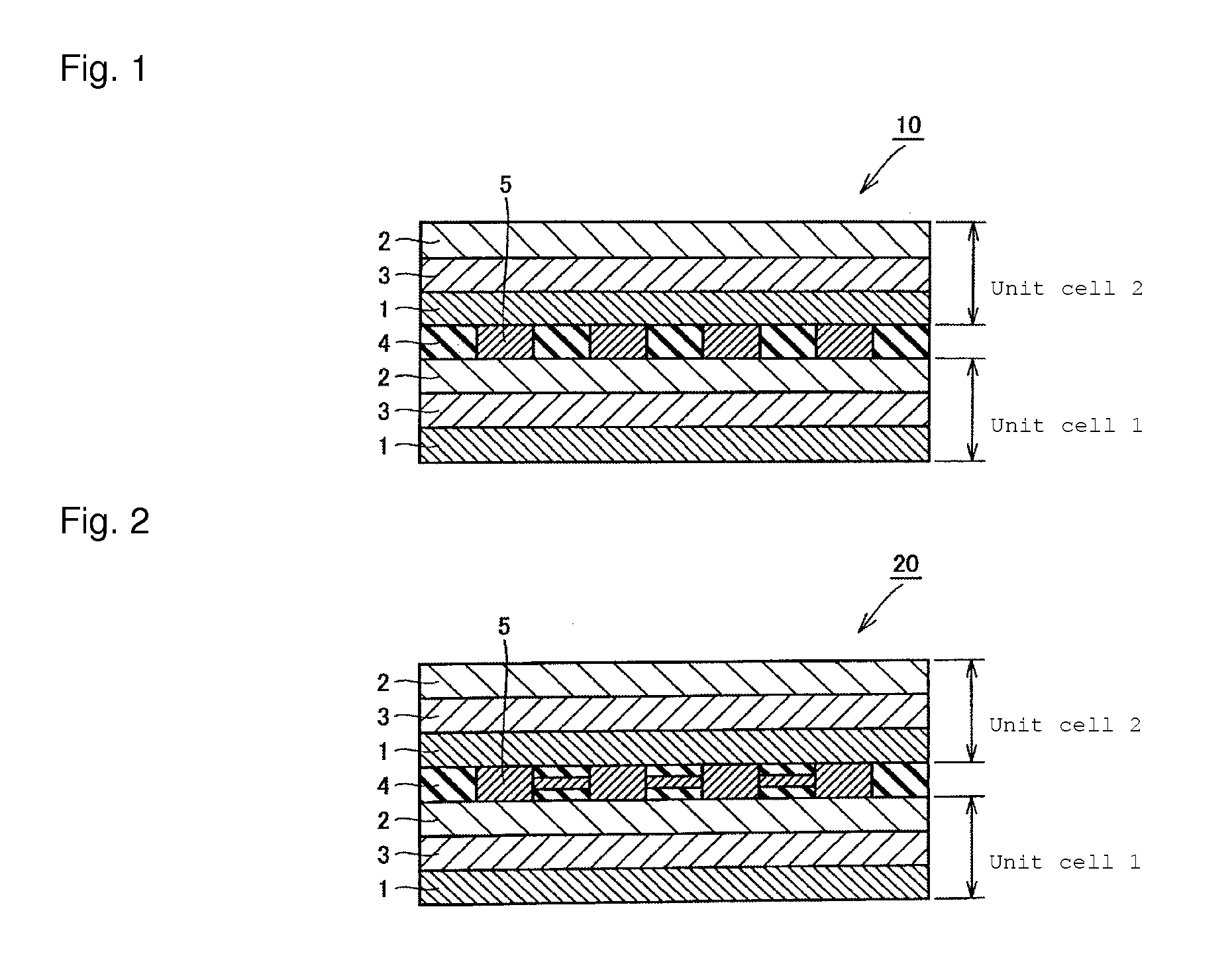
[0047]Referring to FIG. 1, in a laminate type solid secondary battery 10, two unit cells 1 and 2 are stacked via an intercellular separation structure body. Each of the unit cells 1 and 2 is constituted with a positive electrode layer 1, a solid electrolyte layer 3, and a negative electrode layer 2 that are sequentially stacked.

[0048]The intercellular separation structure body is constituted with an insulating layer 4 serving as an insulating section and a plurality of electroconductive sections 5 formed within the insulating layer 4. The insulating layer 4 electroconductively and ion-conduc...

second embodiment

[0053]Next, a laminate body constituting a second basic structure of the laminate type solid secondary battery will be described as the second embodiment of this invention.

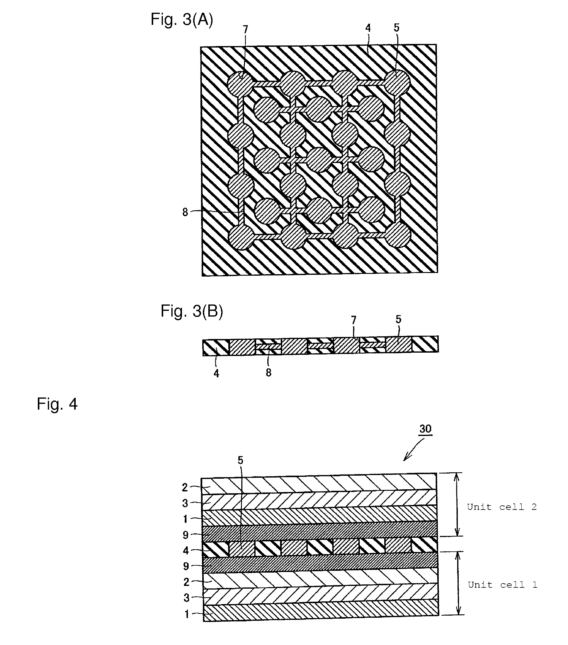
[0054]Referring to FIG. 2, in a laminate type solid secondary battery 20, the two unit cells 1 and 2 are stacked via an intercellular separation structure body in the same manner as in FIG. 1. Referring to FIG. 3, a first through-hole 7 and a second through-hole 8 are formed in the insulating layer 4. The second through-hole 8 is formed so that a plurality of adjacent first through-holes 7 may be in communication with each other. The first through-hole 7 is formed so as to penetrate through the insulating layer 4 in the stacking direction, and the second through-hole 8 is formed so as to penetrate through the insulating layer 4 by extending in a direction approximately orthogonal to the stacking direction, that is, the plane direction. The second through-hole 8 forms a hollow structure in the insulating layer 4. B...

third embodiment

[0059]Next, a laminate body constituting a third basic structure of the laminate type solid secondary battery will be described as the third embodiment of this invention.

[0060]Referring to FIG. 4, in a laminate type solid secondary battery 30, the two unit cells 1 and 2 are stacked via an intercellular separation structure body in the same manner as in FIG. 1. In the unit cell 1, a current-collecting layer 9 having an electric conduction property is formed on the surface of the negative electrode layer 2 disposed on the side of the intercellular separation structure body, that is, on the side of the insulating layer 4. In the unit cell 2, another current-collecting layer 9 having an electric conduction property is formed on the surface of the positive electrode layer 1 disposed on the side of the intercellular separation structure body, that is, on the side of the insulating layer 4. In other words, the unit cells 1 and 2 are constituted by disposing the current-collecting layer 9 h...


PUM

PropertyMeasurementUnit
Electrical conductoraaaaaaaaaa

Abstract

An intercellular separation structure body capable of electrically connecting a plurality of unit cells that include a laminate type solid secondary battery with each other, and capable of ion-conductively insulating a positive electrode layer and a negative electrode layer in two adjacent unit cells, as well as a laminate type solid secondary battery provided with the same. The intercellular separation structure body is an intercellular separation structure body disposed between a plurality of unit cells each of which includes a positive electrode layer, a solid electrolyte layer, and a negative electrode layer that are sequentially stacked in a laminate type solid secondary battery. This intercellular separation structure body includes an insulating layer that electroconductively and ion-conductively insulates the plurality of unit cells from each other and an electroconductive section that is formed within the insulating layer and electrically connects the plurality of unit cells with each other.

Description

CROSS REFERENCE TO RELATED APPLICATIONS[0001]The present application is a continuation of International application No. PCT / JP2010 / 003473, filed May 25, 2010, which claims priority to Japanese Patent Application No. 2009-215457, filed Sep. 17, 2009, the entire contents of each of which are incorporated herein by reference.FIELD OF THE INVENTION[0002]The present invention generally relates to an intercellular separation structure body and a laminate type solid secondary battery provided with the same, and more particularly to an intercellular separation structure body for connecting unit cells in series in a laminate type secondary battery and a laminate type solid secondary battery provided with the same.BACKGROUND OF THE INVENTION[0003]In recent years, a battery, particularly a secondary battery, is used as a power source of a portable electronic apparatus such as a portable phone, a portable personal computer, or the like. As one example of a secondary battery, a lithium ion secon...

Claims


Application Information

Patent Timeline
IPC IPC(8): H01M6/46H01M10/04H01M6/00H01M2/16H01M10/02H01M50/528H01M50/434H01M50/529
CPCH01M2/1646H01M2/18H01M2/22H01M4/66H01M4/70Y10T29/49108H01M10/0562Y02E60/122H01M2/204H01M2/24H01M2/202H01M10/052Y02E60/10H01M50/528Y02P70/50H01M50/434H01M4/64H01M50/529
Inventor OUCHI, MASUTAKAWATANABE, KOICHINISHIDA, KUNIONISHIDA, HITOMIIWAGUCHI, TAKAFUMI
Owner MURATA MFG CO LTD
Learn More