Elastomeric spring pulley assembly for rotary devices

a technology of elastomeric springs and pulleys, which is applied in the direction of couplings, mechanical equipment, hoisting equipment, etc., can solve the problems of spring failure, limited compression of springs, and loss of the ability to attenuate and cushion impact, so as to achieve smooth counteract the changes and greater control of relative rotation

Inactive Publication Date: 2012-07-05
C T DRIVES
View PDF21 Cites 31 Cited by
  • Summary
  • Abstract
  • Description
  • Claims
  • Application Information

AI Technical Summary

Benefits of technology

[0013]In a more specific aspect, the mechanical stop comprises relatively moveable components respectively associated with the pulley and the hub that engage to prevent rotation of the pulley and the hub by more than said predetermined amount. The pulley assemblies operate bidirectionally in both drive and drag directions, and afford predetermined amounts of cushioning and attenuation of the effects of sudden relative rotational velocity changes due to relative accelerations and, if desired, decelerations of a pulley driver a

Problems solved by technology

Over-compression caused the elastomeric material from which the springs are formed to deteriorate and lose its resiliency, thereby resulting in spring failure and a loss of the abil

Method used


Image

  • Elastomeric spring pulley assembly for rotary devices
  • Elastomeric spring pulley assembly for rotary devices
  • Elastomeric spring pulley assembly for rotary devices

Examples


first embodiment

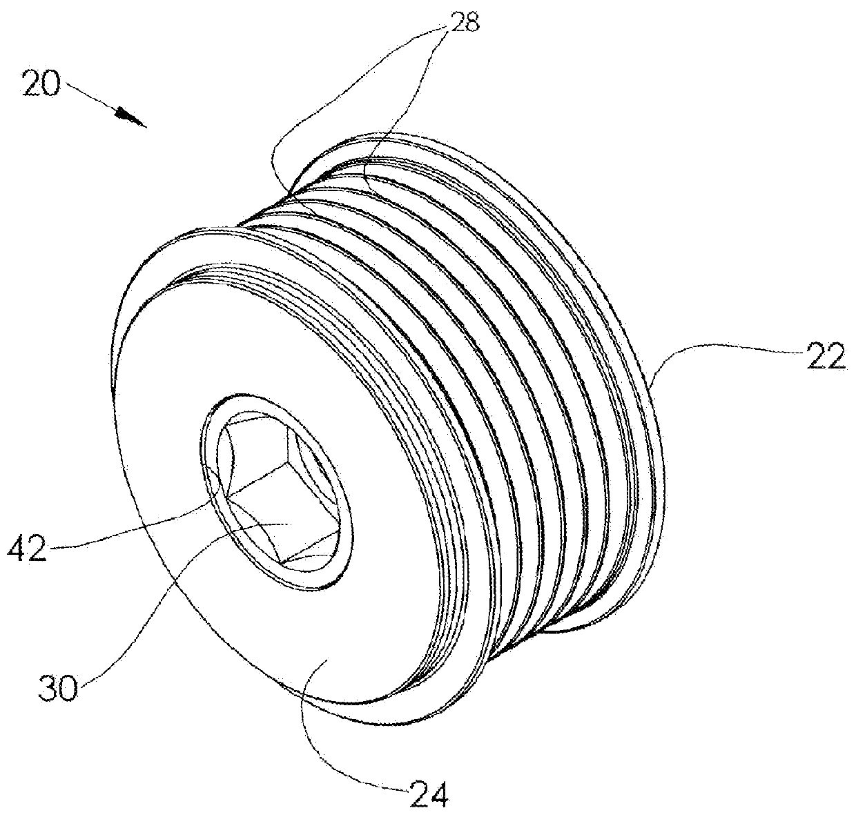
[0028]Generally, the pulley assemblies according to the invention employ elastomeric (polymer) springs and are operative in both driving and drag directions. They allow the pulley to accelerate or decelerate suddenly and rotate relative to the hub and shaft, i.e., displace, by a predetermined relative angular rotation, as will be described, while remaining resiliently coupled. (Some embodiments of the present invention, however, such as FIGS. 1-7, may not employ springs and resilient coupling operating in the drag direction, and may over-run in this direction.) Thus, the sudden acceleration or deceleration of the pulley is not transmitted to the shaft. Rather, the resilient coupling between the pulley and the hub / shaft permits substantially instantaneous relative angular rotation or displacement between the pulley and shaft. When the relative angular velocity of the pulley and the rotational deviation between the pulley and the shaft increases, as during a driving cycle (e.g., combu...

second embodiment

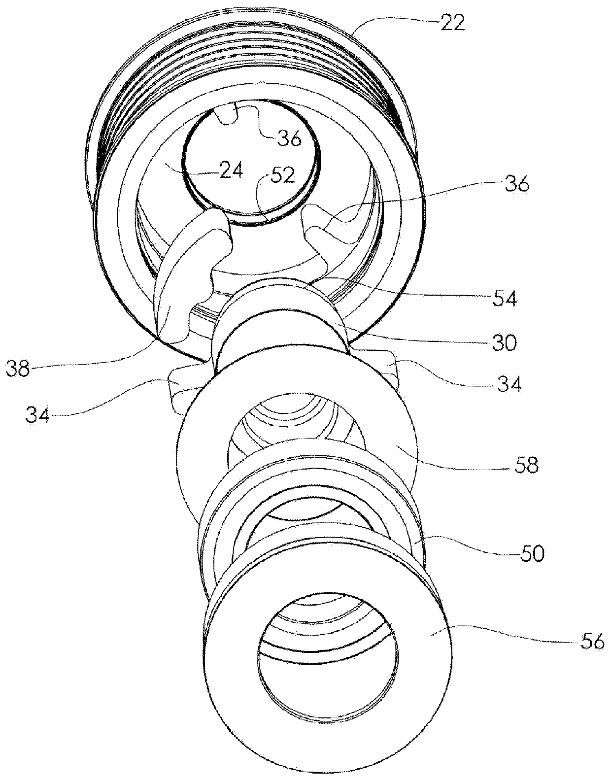
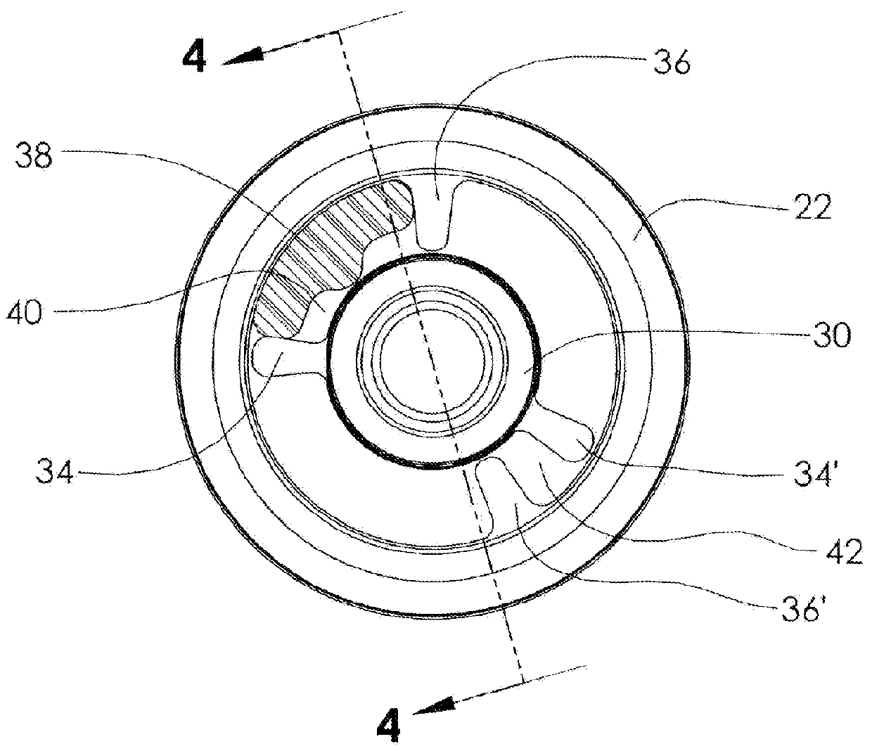
[0045]FIGS. 8A-B also incorporates a mechanical stop arrangement to limit relative rotation of the pulley and hub / shaft in a driving direction to a predetermined amount that prevents over-compression of the springs. This stop arrangement comprises forming at least one of the cylindrical springs 138′ between a pair of projections 134′, 136′ to have an axial portion of its outer side removed to form a flat 146 adjacent to the inner circumferential surface of the pulley, as shown in FIG. 8A, and disposing a substantially flat hard, non-compressible, insert 148, such as a metal bar, (shown in FIG. 8B) into the space between the flat 146 and the inner surface of the pulley, as shown. Insert 148 functions as a mechanical stop that prevents full compression of the springs and affords a predetermined controlled amount of compression. Upon rotation of the pulley in a driving direction (CCW in the figure) relative to the hub, as during a combustion stroke of the engine, pulley projections 136...


PUM


Abstract

A pulley assembly for a rotary device such as an automotive alternator comprising a pulley, a hub, and one or more elastomeric springs to cushion and attenuate the effect of sudden rotational velocity variations of the pulley and the hub. Premature spring failure is prevented by a mechanical stop arrangement that limits the amount of relative rotation between the pulley and hub to prevent over-compression of the springs.

Description

BACKGROUND[0001]This invention relates generally to pulley assemblies for rotary devices, and more particularly to pulley assemblies for driving rotary devices, such as automotive alternators, which use elastomeric springs to cushion and attenuate the effects of abrupt rotational velocity changes[0002]Some systems which employ rotary prime movers as drivers for providing rotational motive power for driving accessory rotary devices are characterized by cyclic dynamic torque characteristics which result in rotational perturbations that are transmitted to the rotary accessory devices. An example of such systems is an internal combustion engine that drives rotary accessory devices such as an alternator, air-conditioning compressor, water pump, etc. Rotation of the engine crankshaft is transmitted via a serpentine or poly-V drive belt system to pulleys attached to the drive shafts of such accessory devices to rotate their shafts. The rotation of an internal combustion engine crankshaft i...

Claims


Application Information

Patent Timeline
IPC IPC(8): F16H55/36
CPCF16F15/1245F16H2055/366F16H2055/363F16H55/36F16F15/1217
Inventor FITZ, FRANK A.
Owner C T DRIVES
Why Eureka
Try Eureka