
System and method for diagnosing a turbocharger

a turbocharger and system technology, applied in the direction of machines/engines, electric control, instruments, etc., can solve the problems of labor-intensive removal or expensive replacement, and the possibility of discovering a turbocharger faul

Inactive Publication Date: 2012-07-05
GENERAL ELECTRIC CO
View PDF8 Cites 12 Cited by
  • Summary
  • Abstract
  • Description
  • Claims
  • Application Information

AI Technical Summary

Benefits of technology

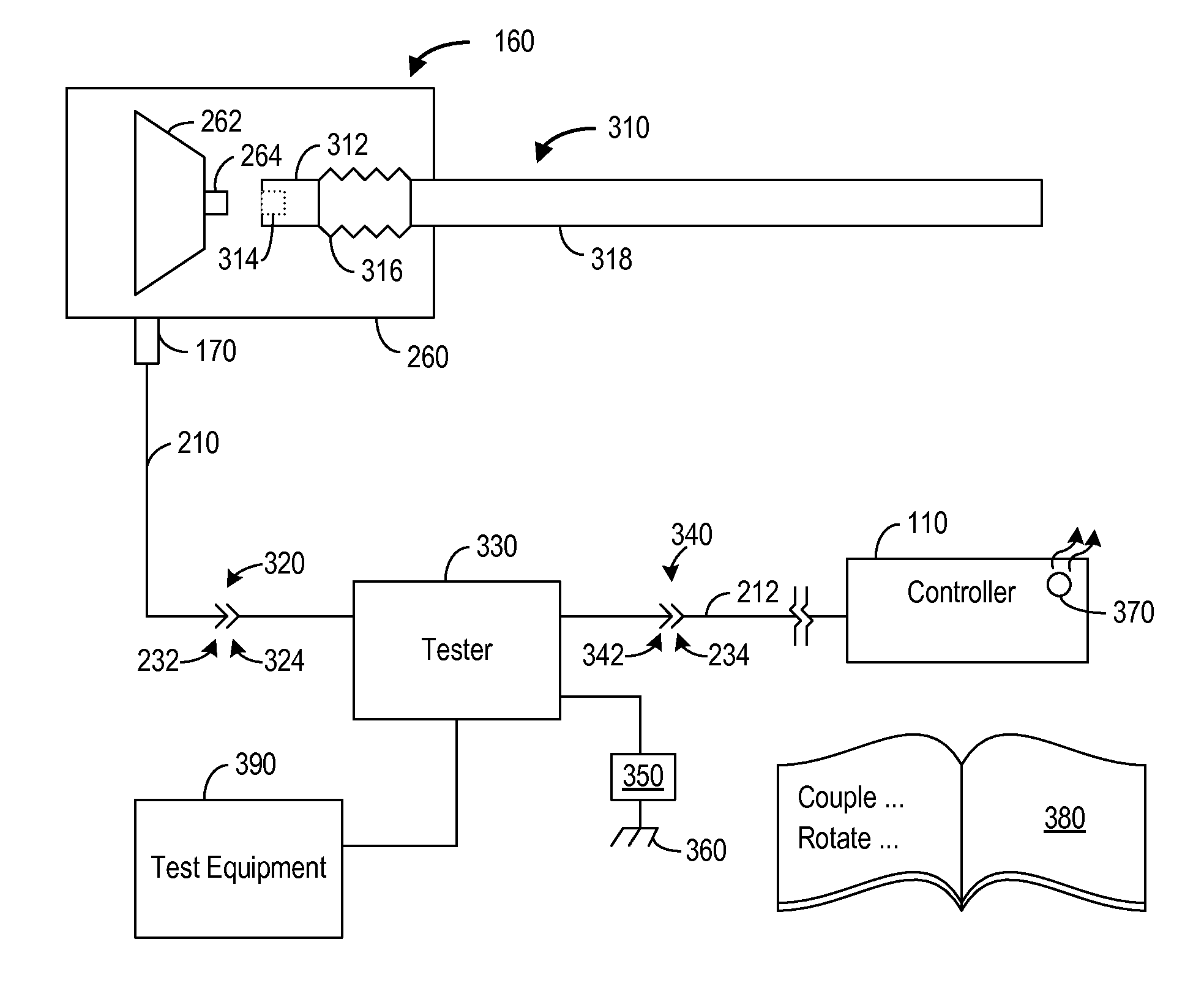
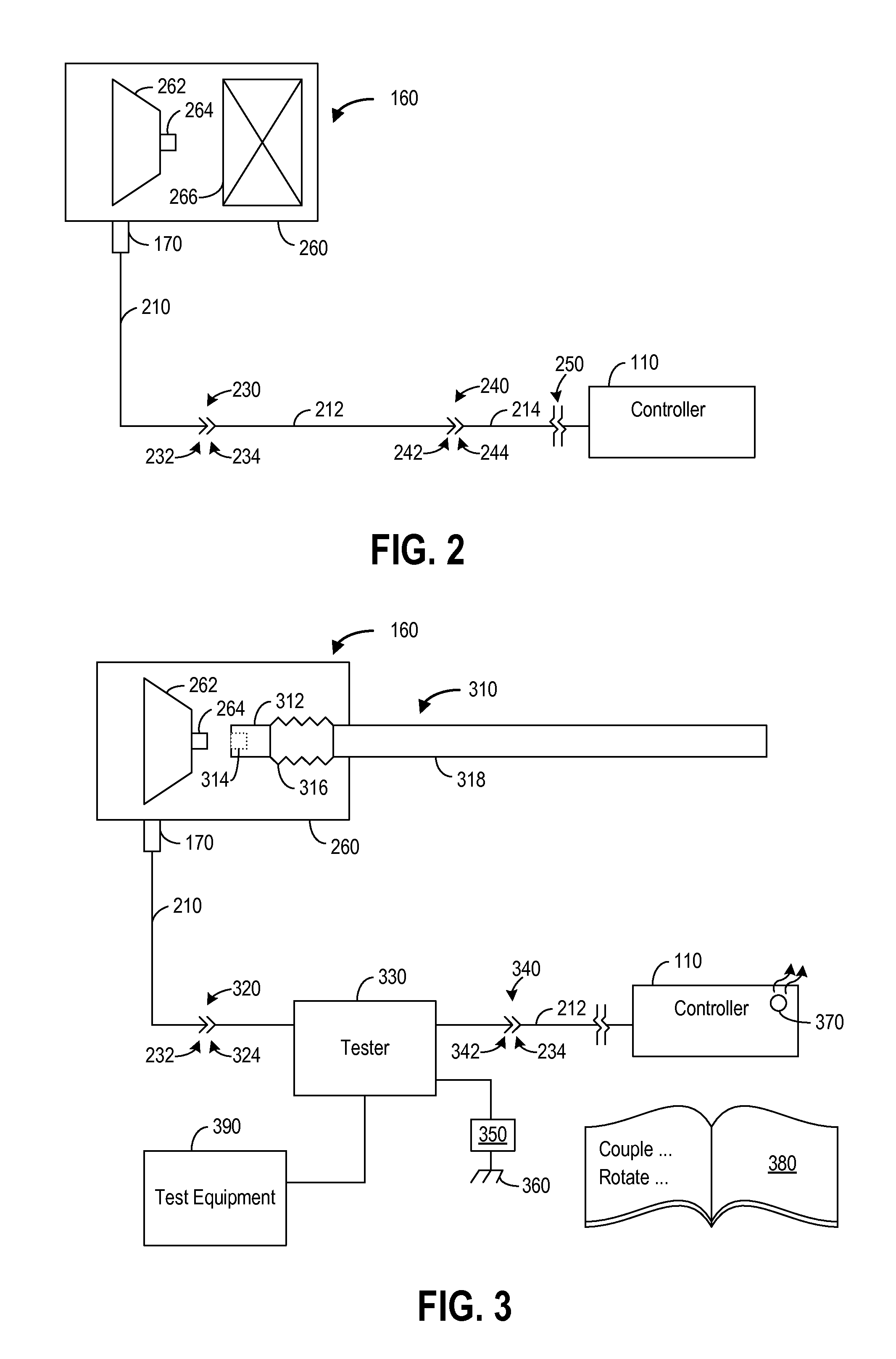
[0007]Thus, in one embodiment, all or substantially all of the electronically diagnosable and visually inspectable parts of the turbocharger system may be diagnosed prior to removal or replacement of any parts of the turbocharger system from the vehicle. For example, a fault may be diagnosed by visually identifying a faulty electrical connector of the turbocharger system prior to removal of the turbocharger system from the vehicle. In this manner, the turbocharger fault may be discovered prior to performing potentially labor intensive removal or expensive replacement of the turbocharger system.
[0008]This brief description is provided to introduce a selection of concepts in a simplified form that are further described herein. This brief description is not intended to identify key features or essential features of the claimed subject matter, nor is it intended to be used to limit the scope of the claimed subject matter. Furthermore, the claimed subject matter is not limited to implementations that solve any or all disadvantages noted in any part of this disclosure. Also, the inventor herein has recognized any identified issues and corresponding solutions.

Problems solved by technology

In this manner, the turbocharger fault may be discovered prior to performing potentially labor intensive removal or expensive replacement of the turbocharger system.

Method used


Image

  • System and method for diagnosing a turbocharger
  • System and method for diagnosing a turbocharger
  • System and method for diagnosing a turbocharger

Examples


Embodiment Construction

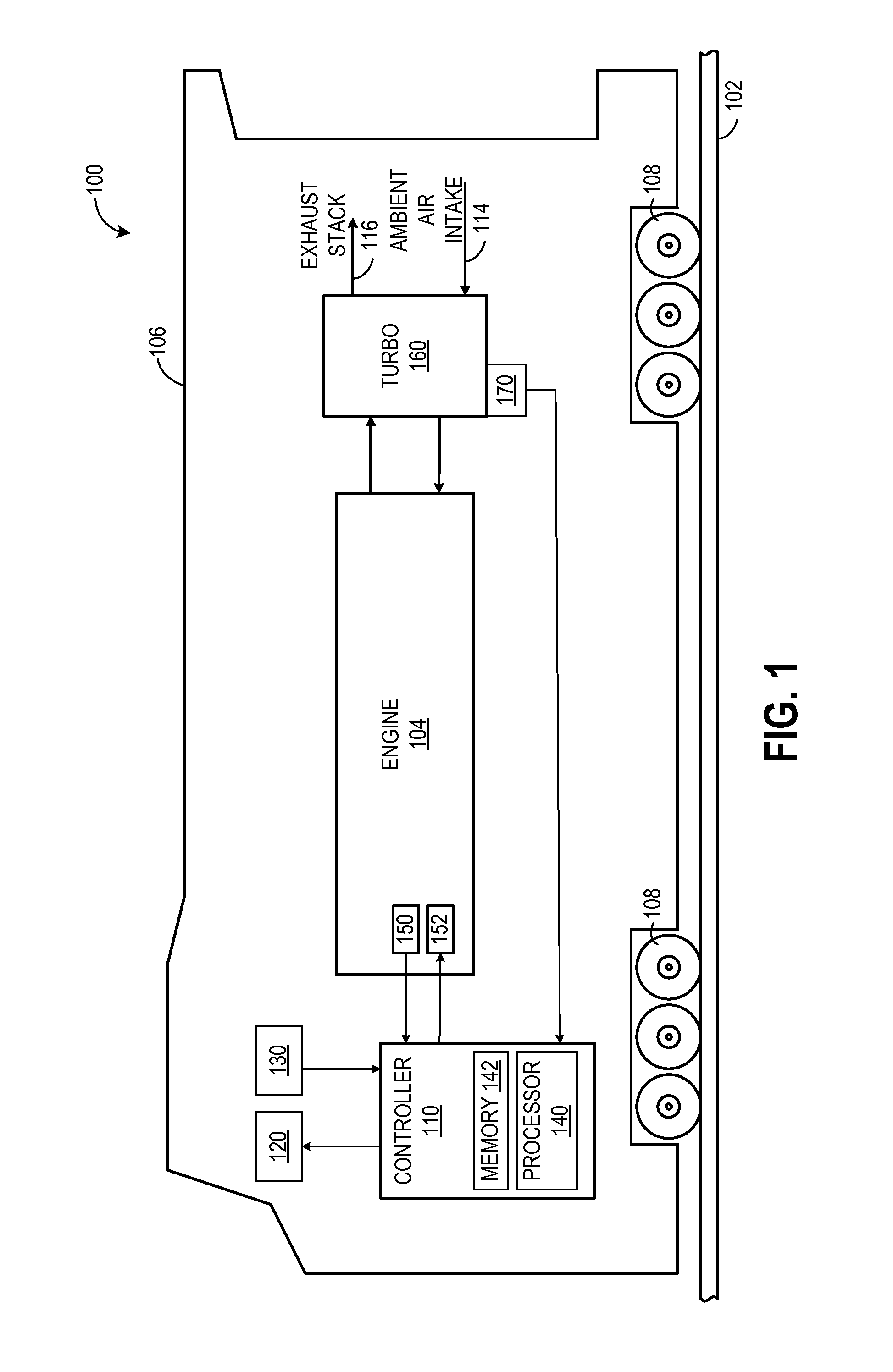
[0017]Some vehicles (such as marine vessels, mining trucks, or the exemplary embodiment of a locomotive as shown in FIG. 1) may include an engine having a turbocharger to increase power output and / or engine-operating efficiency by increasing charge density of air during combustion. The vehicle may further include a controller connected to the turbocharger system through one or more wiring harnesses, such as illustrated in the exemplary embodiment of FIG. 2. The controller may monitor and adjust the turbocharger system. For example, one or more components of the turbocharger system may fail at some time during the operation of the vehicle, and onboard electronic diagnostics of the controller may record the fault. For some turbocharger system failures, the onboard electronic diagnostics may record the root cause of the fault, but for other failures, the root cause may not be identified by the onboard electronic diagnostics. When the root cause cannot be determined by the onboard elect...


PUM


Abstract

Methods and systems are provided for diagnosing a fault of a turbocharger of a vehicle system. The turbocharger system comprises a rotary component and a wiring harness including a plurality of signals. In one embodiment, a diagnosis kit comprises a tester, a manipulation tool, and a plurality of human readable instructions. The tester includes a connector operable to connect to the wiring harness and a plurality of connectors. The tester is configured to receive signals from the wiring harness for use in diagnosing the fault source. The manipulation tool couples to and decouples from the rotary component and the tool is operable to rotate the rotary component when the tool is coupled to the rotary component. The plurality of human readable instructions includes information on how to diagnose the fault of the turbocharger system using the tester and the physical manipulation tool.

Description

CROSS REFERENCE TO RELATED APPLICATIONS[0001]This application claims priority to U.S. App. Ser. No, 61 / 429,605, filed Jan. 4, 2011, the entirety of which is hereby incorporated by reference.FIELD[0002]Embodiments of the subject matter disclosed herein relate to a diagnostic kit, system, and a method for diagnosing a turbocharger system.BACKGROUND[0003]An off-highway vehicle, such as a locomotive, a mining truck, or a marine vehicle, may include an engine having a turbocharger system. The turbocharger system may fail at some time during the operational lifetime of the vehicle, but the cause of the fault may not be readily apparent. The vehicle may include onboard electronic diagnostics to determine fault causation. However, some faults cannot be identified by the electronic diagnostics and other corrective actions must be taken to identify the root cause. Current solutions include complete removal and replacement of the faulty turbocharger system, or removal and disassembly of the tu...

Claims


Application Information

Patent Timeline
IPC IPC(8): G01M15/04
CPCF02B39/16G01M15/09Y02T10/40F02D41/221
Inventor ANDERSON, LARRY GENE
Owner GENERAL ELECTRIC CO
Learn More