Solar heat pipe heat exchanger

a heat exchanger and solar energy technology, applied in indirect heat exchangers, thermal-pv hybrid energy generation, lighting and heating apparatus, etc., can solve the problems of inefficient heat transfer from the heat pipe condenser to the heat transfer fluid flowing through the large diameter header pipe, inconvenient use of tall or thick structures, etc., to optimize electrical generation, optimize use, and reduce the effect of cos

Inactive Publication Date: 2012-07-12
KMETOVICZ RONALD E +1
View PDF3 Cites 30 Cited by
  • Summary
  • Abstract
  • Description
  • Claims
  • Application Information

AI Technical Summary

Benefits of technology

[0023]The integrated solar thermal and photovoltaic design provides electrical output equivalent to that of photovoltaic panels not having heating capability; plus, the thermal output is nearly equivalent to a solar panel without electrical capability. This combination provides low cost electricity and heat. A computer control may optimize the use of either the electric or thermal system. The header heat exchanger can be supplied with cooled heat transfer fluid not c

Problems solved by technology

Simple to construct solar heat pipe designs currently on the market fail to optimally mate a constant diameter heat pipe to the header assembly.
As such, if piping were used, the header diameter would be large and heat transfer from the heat pipe condenser to the heat transfer fluid flowing through the large diameter header pipe becomes inefficient.
No header implementation currently exists that accepts a constant diameter heat pipe and efficiently transfers the heat from the heat pipe condenser to the heat transfer fluid circulating within the header.
The current design techniques tend to produce a tall or thick structure not suitable for use in solar panels.
Efficient heat transfer from the heat pipe condenser to the heat transfer fluid in the header assembly presents significant design challenges.
The area of the heat pipe condenser in contact with the heat transfer fluid within the header tends to be small when the heat pipe condenser is inserted into a small pipe, and thus, resulting in very poor heat transfer.
Solar vacuum tube designs use a single top header design which proves to be thermally inefficient when used with non-vacuum insulate

Method used


Image

  • Solar heat pipe heat exchanger
  • Solar heat pipe heat exchanger
  • Solar heat pipe heat exchanger

Examples


Embodiment Construction

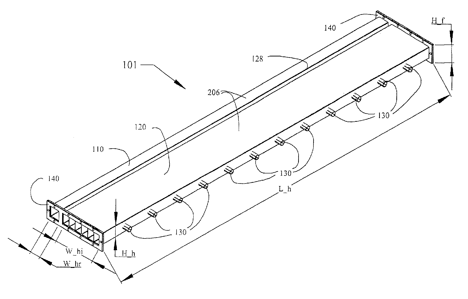
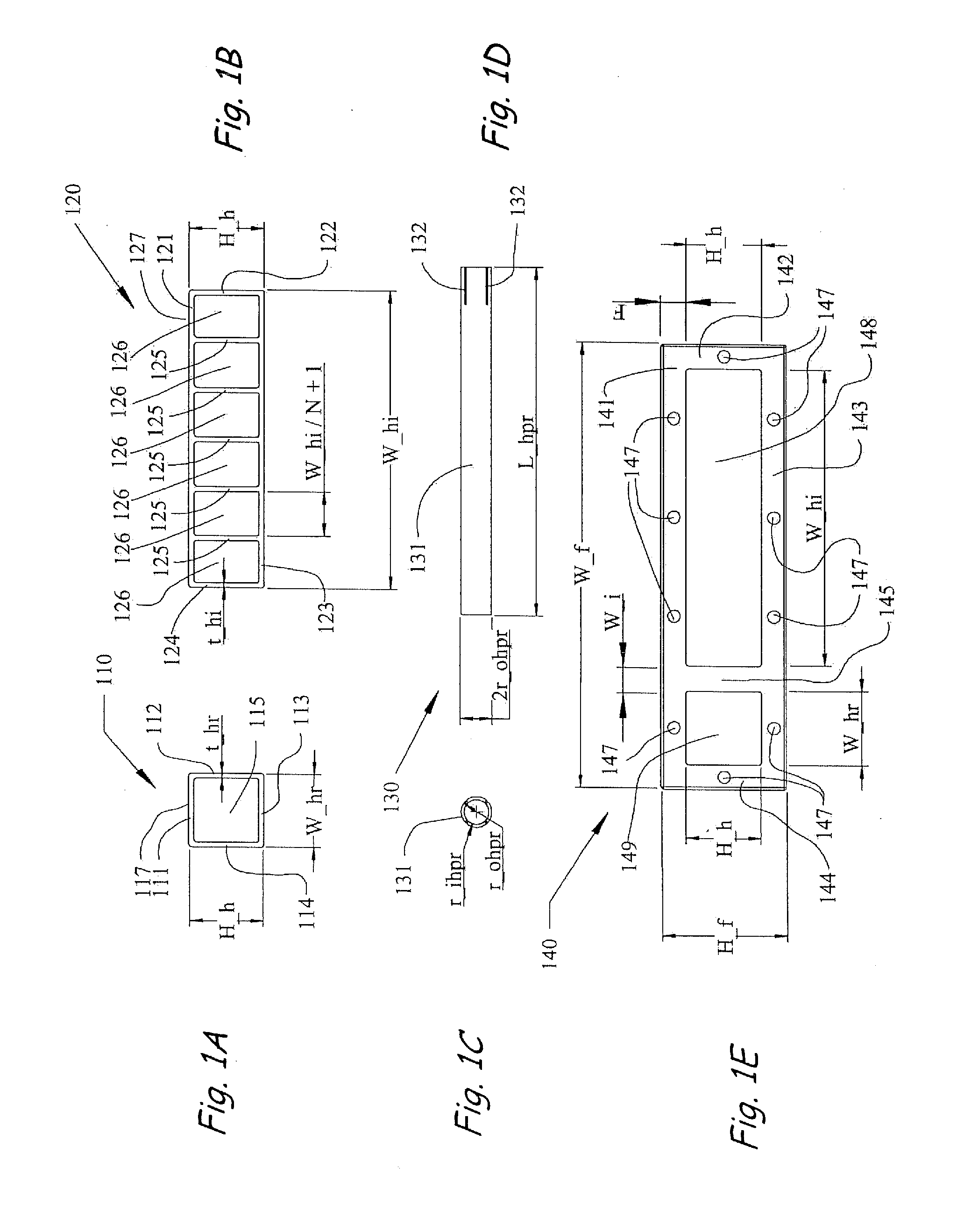
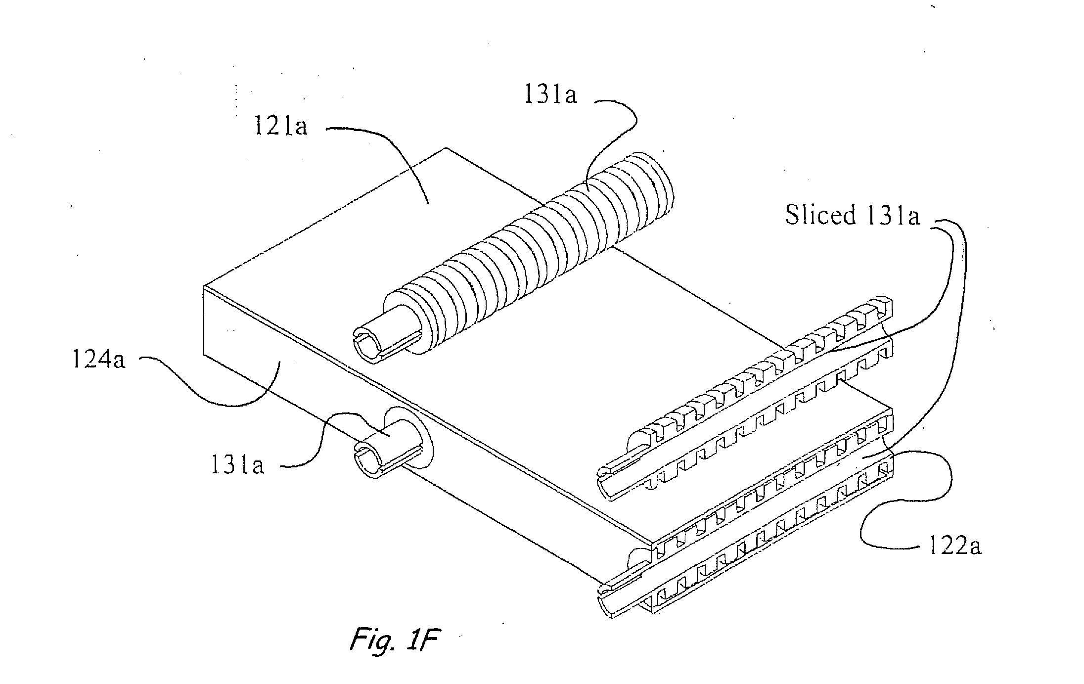
[0038]FIGS. 1A-E are a set of detail, side views of a header assembly 101 showing detail of the header return 110, header inlet 120, heat pipe receiver 130, and header flange 140 components.

[0039]The header return 110 transports returning heat transfer fluid 11 within the header assembly 101 (See FIGS. 2, 5 and 9). The header return 110 is W hr wide, H_h high, and L_h long, and may be Ruined by extruding a suitable material such as aluminum. The header return top wall 111, header return inside side wall 112, header return bottom wall 113 and header return side wall 114 have thickness t_hr and faun the return fluid channel 115. The header return inside side wall 112 is located in near proximity to the header inlet inside side wall 124. The space between the header return inside side wall 112 and the header. inlet inside side wall 124 having width W_i, thermally isolates the header return 110 from the header inlet 120. The header return top wall 111 may be coated with a high absorbtiv...


PUM


Abstract

This invention relates to the process of collecting heat and removing heat from a heat pipe for solar energy applications. More specifically, this invention is a solar energy system that elegantly couples a heat pipe and a single header heat transfer assembly that has the capability of interchangeable operational designs using solar collector panel, solar vacuum tube, or integrated solar thermal and photovoltaic array configurations. The header assembly is structurally and thermally connected to the heat pipe by a heat pipe receiver which surrounds the condenser end of the heat pipe and plugs into the interior of the header assembly.

Description

DESCRIPTION[0001]This application claim priority of Provisional Application Ser. No. 61 / 242,198, filed Sep. 14, 2009, the entire disclosure of which is incorporated herein by this reference.BACKGROUND OF THE INVENTION[0002]1. Field of the Invention[0003]The present invention relates to a solar heat pipe heat exchanger and, more particularly, to a single header solar heat pipe heat exchanger with a header assembly having a plurality of inlet fluid channels formed by heat transfer fins and a single return fluid channel for the circulation of heat transfer fluid, and having at least one heat pipe attachment that contains a working fluid operating in a closed loop system within the heat pipe. Each heat pipe is attached to the header assembly at a connection junction by means of a single clamp, wherein collected heat is transferred from the heat pipe to the header assembly by the process of evaporation and condensation. The heat pipe heat exchanger has the capability of interchangeable o...

Claims


Application Information

Patent Timeline
IPC IPC(8): F28D15/02F24S10/95
CPCY02E10/44H02S40/44Y02E10/60F24J2/32F24S10/95Y02E10/50Y02E10/40
Inventor KMETOVICZ, RONALD E.SANDERS, STEVEN N.
Owner KMETOVICZ RONALD E
Why Eureka
Try Eureka