Light-emitting diode lamp with an improved leadframe

Active Publication Date: 2012-07-12
LEXTAR ELECTRONICS CORP
View PDF3 Cites 4 Cited by
  • Summary
  • Abstract
  • Description
  • Claims
  • Application Information

AI Technical Summary

Benefits of technology

[0010]An object of this invention is to provide an improved leadframe that can increase the rate of heat dissipation for a light-emitting diode.
[0011]Another object of this invention is to provide a packaging cup incorporating a leadframe that can increase the rate of heat dissipation for a light-emitting diode.
[0012]Yet another object of this invention is to provide a light-emitting diode lamp having a leadframe that can increase the rate of heat dissipation for a light-emitting diode.

Problems solved by technology

Moreover, due to the accumulated heat, the cup body 112 is prone to deform and change in its intrinsic properties, and can even release toxic gases as a result of chemical reaction caused by heat.

Method used


Image

  • Light-emitting diode lamp with an improved leadframe
  • Light-emitting diode lamp with an improved leadframe
  • Light-emitting diode lamp with an improved leadframe

Examples


Embodiment Construction

[0026]Before the present invention is described in greater detail with reference to the accompanying preferred embodiment, it should be noted herein that like elements are denoted by the same reference numerals throughout the disclosure.

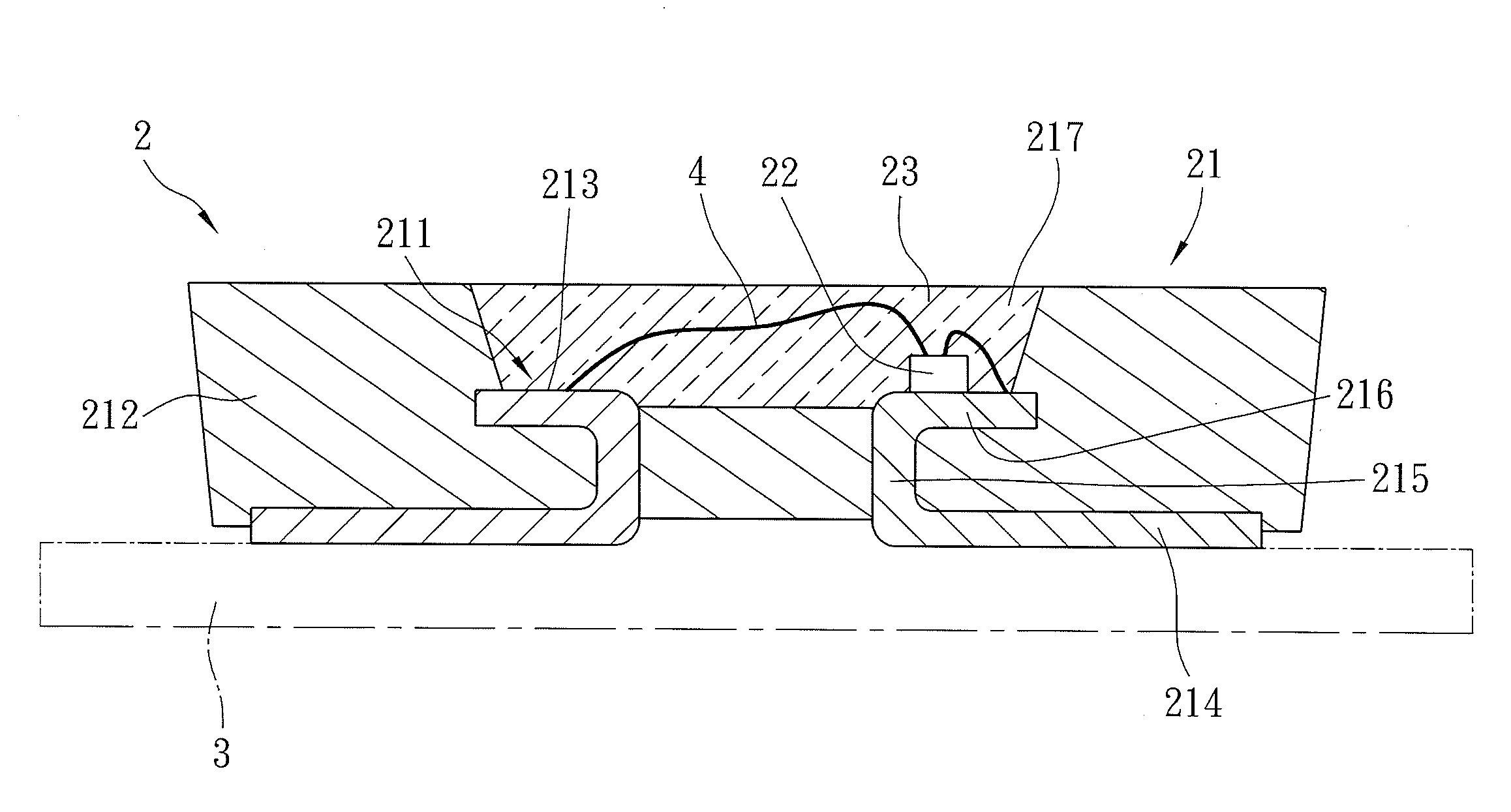
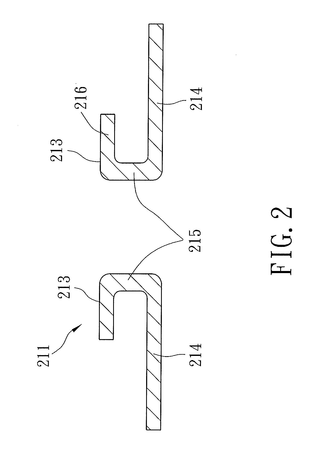
[0027]Referring to FIG. 2, a leadframe 211 according to the first preferred embodiment of this invention, which may be used to carry a light-emitting diode chip 22 (see FIG. 4), includes two spaced apart conductive legs 213 that are made of a metal material and that provide fast heat dissipation characteristics.

[0028]Each of the conductive legs 213 includes a base section 215, a first extension section 214 extending from a bottom end of the base section 215 in a direction away from the other one of the conductive legs 213, a second extension section 216 that extends from a top end of the base section 215 in the same direction as the respective first extension section 214 and that is adapted to fix the light-emitting diode chip 22 thereto. Each of the...


PUM


Abstract

A leadframe includes two spaced apart conductive legs, each of which includes a base section, and a first extension section extending from a bottom end of the base section in a direction away from the other one of the conductive legs. At least one of the conductive legs further includes a second extension section that extends from a top end of the base section thereof in the same direction as the first extension section for fixing the light-emitting diode chip. The heat generated by the light-emitting diode chip can be dissipated through a shortest heat-dissipating route, thereby increasing the heat-dissipating rate.

Description

CROSS REFERENCE TO RELATED APPLICATION[0001]This application claims priority of Taiwanese Application No. 100100961 filed on Jan. 11, 2011.BACKGROUND OF THE INVENTION[0002]1. Field of the Invention[0003]The invention relates to a light-emitting diode lamp, and more particularly to a leadframe for a light-emitting diode lamp.[0004]2. Description of the Related Art[0005]Referring to FIG. 1, light-emitting diode lamp 1 comprises a packaging cup 11, a light-emitting diode chip 12 and a transparent encapsulant 13.[0006]The packaging cup 11 comprises a leadframe 111 and a cup body 112. The leadframe 111 comprises two spaced apart conductive legs 113, each of which includes a base section 114, and a first extension section 115 extending from a bottom end of the base section 115 in a direction toward the other one of the conductive legs 113, and a second extension section 116 extending from a top end of the base section 115 in a direction toward the other one of the conductive legs 113. The...

Claims


Application Information

Patent Timeline
IPC IPC(8): H01L33/50
CPCH01L33/486H01L33/62H01L33/647H01L2224/48091H01L2224/48247H01L2224/16245H01L2224/45144H01L2924/00014H01L2924/00H01L33/10
Inventor CHEN, WEI-ANCHOU, YEN-CHIH
Owner LEXTAR ELECTRONICS CORP
Why Eureka
Try Eureka