Muffle convection brazing/annealing system

Inactive Publication Date: 2000-11-21
SECOWARWICK
View PDF10 Cites 13 Cited by
  • Summary
  • Abstract
  • Description
  • Claims
  • Application Information

AI Technical Summary

Benefits of technology

A plurality of towers are provided, each being formed integrally with the roof of the muffle in each brazing zone and are mounted movably relative to the top wall of the heating chamber A plurality of fans are provided, each being mounted and sealed in a corresponding one of the plurality of towers for creating an atmosphere convection current in each of

Problems solved by technology

The use of the inner liner suffers from the disadvantage in that it is required to be rigidly positioned with respect to fans, doors, and heating/cooling devices since these items are mounted and sealed to the furnace outer shell.
Another drawback lies in the fact that the need for rigid mounting of the inner liner imposes stresses thereon as a result of differential thermal expansion and contraction between the inner liner and the furnace casing.
While various mechanisms have been used heretofore so as to absorb or counteract the stresses due to the differential expansion and contraction, these stresses eventually lead to destruction of the integrity of the liner due to the temperatures normally encountered in the brazing and annealing processes.
This problem becomes even more complex because replacement of the liner then becomes necessary which is a very expensive task since the furnace must essentially be completely disassembled for removal of the existing liner and building of a new one in its place.
Moreover, another difficulty results from the necessity of

Method used


Image

  • Muffle convection brazing/annealing system
  • Muffle convection brazing/annealing system
  • Muffle convection brazing/annealing system

Examples


Embodiment Construction

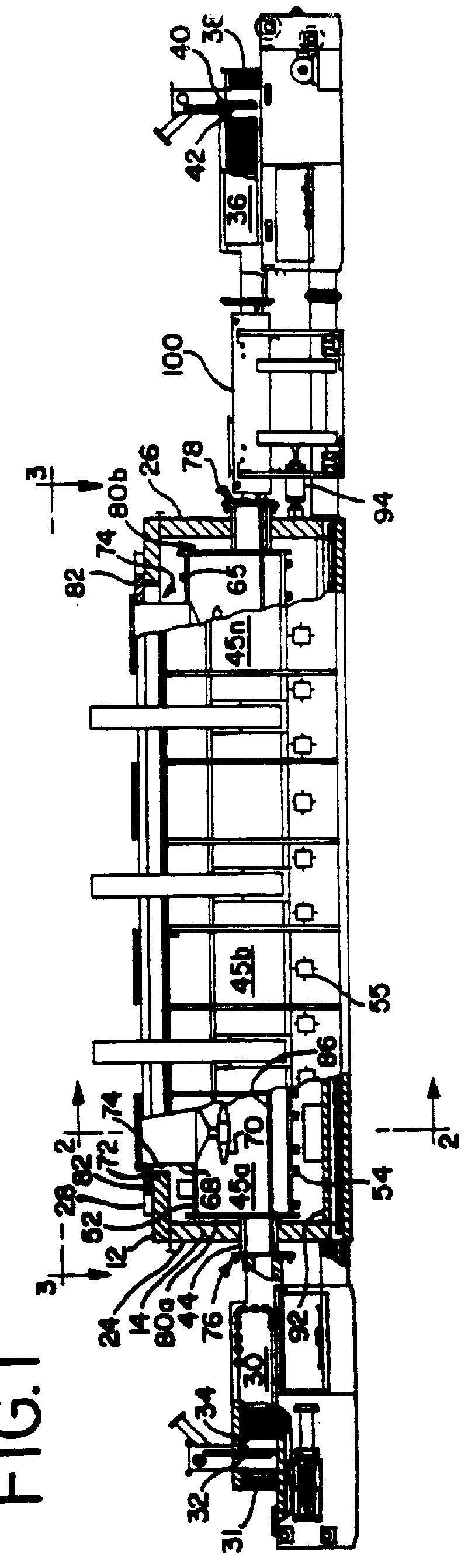
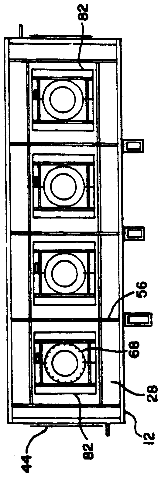
Referring now in detail to the drawings, there is illustrated in FIGS. 1 through 3 an improved muffle convection brazing / annealing furnace 10 which is constructed in accordance with the principles of the present invention. The muffle convection furnace is formed of a sheet metal outer shell 12 which is lined with a layer 14 of insulating refractory material on its interior to define an insulated heating space or chamber 16. The muffle furnace includes a bottom wall 18, a pair of side walls 20 and 22, a front wall 24, a rear wall 26 and a top wall or roof 28. Extending longitudinally and upstream of the front wall 24, there is provided an entrance chamber 30 having atmospheric curtains 31 formed therein and a front door 32 for covering an entrance opening 34. Similarly, there is provided an exit chamber 36 extending longitudinally and downstream of the rear wall 26 which is formed with atmospheric curtains 38 and a rear door 40 for covering an exit opening 42. The front and rear door...


PUM

PropertyMeasurementUnit
Temperatureaaaaaaaaaa
Diameteraaaaaaaaaa
Efficiencyaaaaaaaaaa

Abstract

A convection muffle furnace for brazing and/or annealing a workpiece includes a muffle having towers formed integrally therewith and being mounted movable relative to a top wall of a furnace. Circulation fans are mounted in the towers so as to move along with the muffle during its expansion and contraction for producing forced convection heat transfer.

Description

BACKGROUND OF THE INVENTIONThis invention relates generally to heat-treating furnaces used for brazing and / or annealing of workpieces. More particularly, it relates to an improved method and apparatus for brazing and annealing of a workpiece which includes a furnace having a muffle formed therein and circulation fans disposed in towers which are an integral part of the muffle so as to produce forced convection heat transfer.As is generally well-known in the art of heat-treating, brazing and annealing require a close tolerance on the temperature control in order to achieve a desired temperature profile or to maintain temperature uniformity within a workpiece. Convection heat transfer has been found to provide faster heating or cooling of the workpiece on a more uniform basis. In such convection heat transfer, the hot gases are typically directed at the workpiece by means of jets or fans, with the fans being the more common means to impart velocity to the gases.Further, the brazing an...

Claims


Application Information

Patent Timeline
IPC IPC(8): B23K1/008F27B9/00F27B9/10F27B9/02F27D1/00F27B9/08F27B9/24F27B9/30F27B9/32F27D7/00F27D7/04F27B9/04F27D99/00
CPCB23K1/008F27B9/029F27B9/082F27B9/084F27B9/243F27D1/0023F27B9/10F27B9/045F27D2099/008F27B9/32F27D2001/0076F27D2007/045
Inventor BOSWELL, JEFFREY W.SCHMIDT, MICHAEL A.
Owner SECOWARWICK
Why Eureka
Try Eureka