Battery System

a battery system and battery technology, applied in the field of battery systems, to achieve the effect of enhancing the reliability of the battery system

Active Publication Date: 2012-07-12
HITACHI LTD
View PDF9 Cites 98 Cited by
  • Summary
  • Abstract
  • Description
  • Claims
  • Application Information

AI Technical Summary

Benefits of technology

[0010]According to the present invention, it is possible to manage change of the battery

Problems solved by technology

However, the Patent Document described above does not extend to contemplation of monitoring of changes of the state of the battery

Method used


Image

  • Battery System
  • Battery System
  • Battery System

Examples


first embodiment

[0072]—The

[0073]While the battery system described in this embodiment is optimized for usage as a power supply system to be mounted in a vehicle, it could also be employed as a power supply system for a railroad vehicle or for an industrial machine. Among such power supply systems, a battery system that is optimum for use as a power supply system for a vehicle will be explained as a representative example. It should be understood that, in the explanation above and below, the term “calculate” refers not only to the operation of calculation, but also is used to include and to mean operations such as storage of values calculated in advance in a memory, reading out of data stored in the memory, obtaining values proved to be suitable by experiment and storing them in the memory, reading out values obtained by experiment from the memory, and so on.

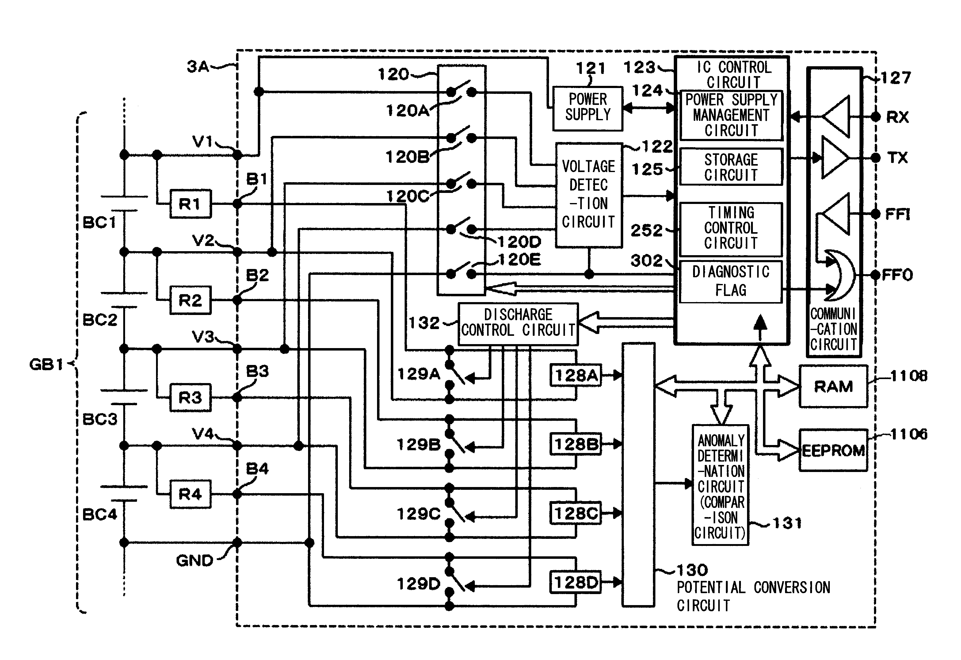
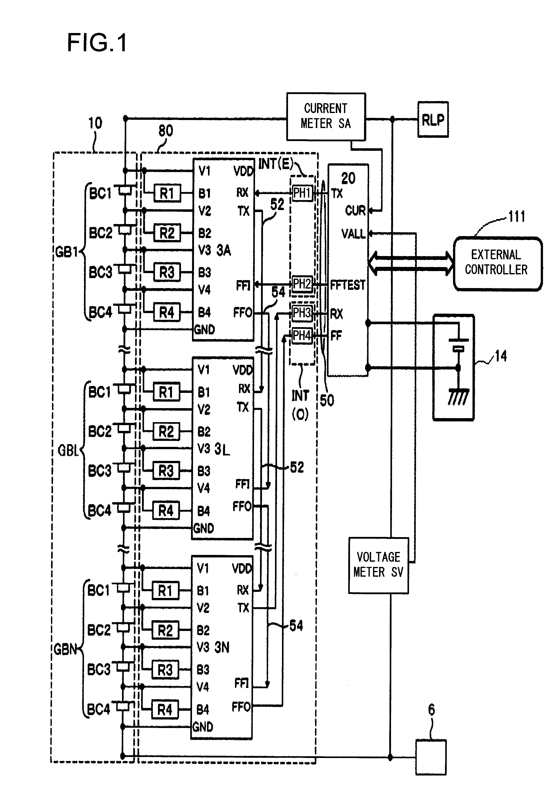
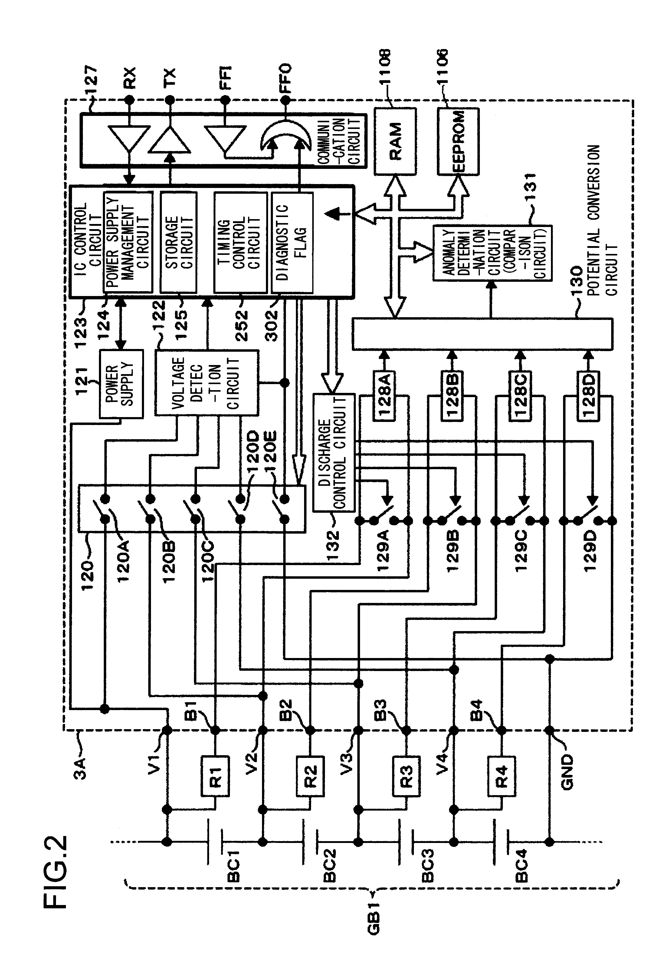
[0074]—Structure of the Battery System—

[0075]FIG. 1 is a block diagram showing an example of the structure of a battery system according to the...

second embodiment

[0216]a method for writing the data into the non-volatile memory and of data updating will now be explained with reference to FIGS. 14 through 23. It should be understood that symbols that are the same as ones in FIG. 13 denote the same structures and functions, or mean that the same operations are performed.

[0217]It should be understood that, if the stored data in the rewritable non-volatile memory 1116 is read out and an anomaly has been found in this data that has been read out, then in a similar manner to the flow in FIG. 13 and to FIG. 21, the data that was updated by the step 1207 is taken as stored data for a second time, and is written into the rewritable non-volatile memory 1116.

[0218]With the method described in FIG. 14, the operation from the step 1202 to the step 1212 for reading out the stored data in the rewritable non-volatile memory 1116 in the step 1202 and shifting this stored data that has been read out to the volatile memory 1117 is the same as the operation desc...


PUM


Abstract

A battery system according to the present invention includes: a battery module comprising a plurality of cell groups connected in series, each comprising a plurality of cells connected in series; a plurality of integrated circuits provided to corresponding each cell group of the battery module, that perform detection of terminal voltages of the cells in the corresponding each cell group, and that also perform diagnosis; and a battery controller that, along with issuing commands to the plurality of integrated circuits, also receives results of detection and results of diagnosis by the plurality of integrated circuits; wherein the battery system comprises a writable non-volatile memory, and data is stored in the writable non-volatile memory specifying usage environment of the battery module, including a maximum voltage or a maximum current of the battery module and history data based upon operation history of the battery module.

Description

TECHNICAL FIELD[0001]The present invention relates to a battery system in which information related to a battery is stored in a rewritable non-volatile memory.BACKGROUND ART[0002]In recent years, demand for higher reliability battery systems for onboard vehicle use has increased, and in particular it has become desirable to enhance the reliability of battery systems that use, for example, lithium cells that store high amounts of power. Battery systems have been proposed that include improved diagnosis functions for heightening their reliability. For example a battery system for onboard vehicle use is disclosed in Patent Document #1 that, in order to enhance reliability, is equipped with a diagnosis circuit that diagnoses whether or not any anomalous condition is occurring in the battery system.Citation ListPatent Literature[0003]Patent Document #1: Japanese Laid-Open Patent Publication 2009-183025.SUMMARY OF INVENTIONTechnical Problem[0004]In Patent Document #1 described above, a te...

Claims


Application Information

Patent Timeline
IPC IPC(8): H02J1/00H02J7/00
CPCB60L3/0046B60L2200/26B60L11/1866B60L2240/545B60L2240/547B60L2240/549B60L2260/44G01R31/3658H01M10/0525H01M10/441H01M10/482H02J7/0021Y02T10/7005Y02T10/7011Y02T10/7044Y02T10/7061H02J7/0016H02J7/0026G11C16/225G11C29/82B60L11/1861B60L58/22G01R31/396B60L58/15B60L58/13B60L58/16B60L58/14Y02E60/10Y02T10/70H02J7/00302H02J7/00306H02J7/005
Inventor OHKAWA, KEIICHIROUEDA, MASAHIRO
Owner HITACHI LTD
Why Eureka
Try Eureka