

Method for analyzing signals from an angle sensor
- Summary
- Abstract
- Description
- Claims
- Application Information
AI Technical Summary
Benefits of technology
Problems solved by technology
Method used
Image

Examples
Embodiment Construction
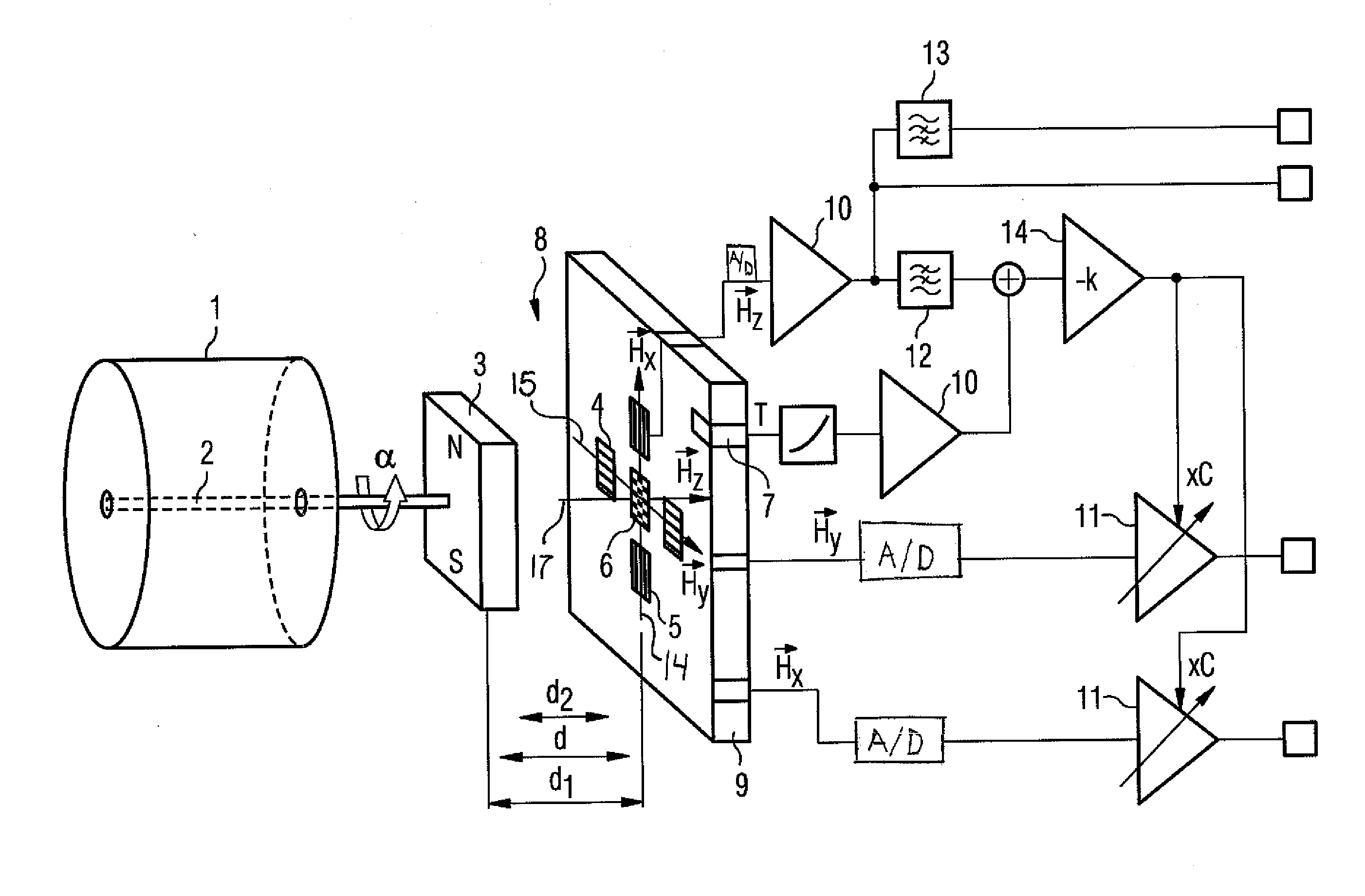
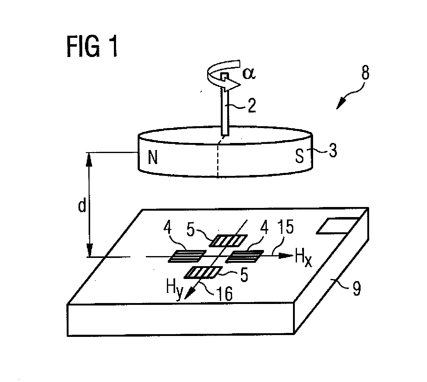
[0023]FIG. 1 shows an angle sensor 8 with a rotor 2 of a brushless electric motor on which a rotatable element 3 for varying a field is arranged. The rotatable element 3 is embodied here as a dipole magnet, wherein the north pole N and the south pole S are shown. Depending on the rotational angle α of the rotor 2 relative to the brushless electric motor, a first linearly independent vector 15 of the field strength denoted here by HX, and a second linearly independent vector 16 of the field strength, denoted here by HY, are induced in the sensor chip 9 of the angle sensor 8. These vectors 15, 16 are generated by a magnetic field and are strictly dependent on the rotational angle α and the associated position of the rotatable element 3. The first sensor element 4, embodied as a vertical Hall element, and the second sensor element 5, embodied as a vertical Hall element in the sensor chip 9, senses the components of the first linearly independent magnetic field vector 15 and of the seco...
PUM
 Abstract
Description
Claims
Application Information