Accommodating intraocular lens and methods of use

a technology of intraocular lens and acuity, applied in the field of intraocular lens, can solve the problems of presbyopia patients losing the ability to focus on the ocular field, the natural lens of the eye becomes thicker and less flexible, and the blindness of adults, so as to improve the calculation of lens power, enhance the effect of accommodating intraocular lens movement and optimal acuity

Inactive Publication Date: 2012-07-12
CORNELL UNIVERSITY
View PDF5 Cites 87 Cited by
  • Summary
  • Abstract
  • Description
  • Claims
  • Application Information

AI Technical Summary

Benefits of technology

[0042]Embodiments of the invention provide an improved accommodating intraocular lens assembly or components thereof, for use in an aphakic eye. In particular, the retainer plate provides natural accommodation benefits. By having a separate retainer plate and optical lens, the inventory of optimal plate size and optic power allows proper sizing for both globe size and dioptic lens power. The diameter of the retainer plate is determined by measurement of the diameter of the natural or crystalline lens before extraction. Lens power is determined separately and independently although the expected lens position post surgery can be derived from the measurement of natural lens dimension. This can improve calculation of lens power. The plate holding the intraocular lens of the present invention also is designed to retard fibrous in-growth, thereby keeping a clear central area for optimal acuity.
[0043]Embodiments of the invention utilize the entire vitreo-zonular diaphragm in order to support and enhance accommodating intraocular lens movement by taking advantage of the uniform pressure exerted by the vitreous body on the lens capsule, and the enhancer or retainer plate / optical lens within the capsule. The retainer plate can augment vitreous support and forward movement of the intraocular lens with accommodation. Embodiments of the invention thus overcome the problems of conventional intraocular lens constructions that utilize only a portion of the vitreous support allowing a bulging to the unsupported sides of the haptics that are used in these conventional intraocular lens constructions, thus dissipating the vitreous support. Ridges may be incorporated into the retainer plate for the purpose of inhibiting epithelial ingrowth. The central opening of the retainer plate is also useful in preventing ingrowth, allowing unimpeded vision and, when necessary, allowing laser opening of a cloudy posterior capsule. The diameter of the retainer plate would be measured preoperatively based on the lens size, which is determined using ultrasound or optical techniques, and should ‘fit’ the posterior capsule and the horizontal dimension of the ciliary diameter as so measured.

Problems solved by technology

Cataracts are currently the leading cause of blindness among adults in the United States.
Presbyopia, a condition in which the natural lens of the eye becomes thicker and less flexible, is also a symptom of the natural aging process.
Patients with presbyopia lose the ability of ocular focus due to lack of accommodation ability of the natural lens.
Bi- or multifocal intraocular lenses, however, suffer from the disadvantage that each image represents only about 40% of the available light, and as much as 20% of the light is lost in scatter.
Accommodating intraocular lenses designed to translate the optic forward in the eye fail to address an important feature of natural lens accommodation.
Available accommodating intraocular lenses fail to possess the capability of undergoing changes in surface curvature.
In other words, available accommodating intraocular lenses do not uniformly flex and move or maintain their flexibility with in-growth of fibroblasts around the supporting capsular structure of the eye.
Furthermore, available accommodating intraocular lenses are not amenable to removal or replacement of the optical lens because of adhesion of the lens to the capsular / zonular support structure of the eye.

Method used


Image

  • Accommodating intraocular lens and methods of use
  • Accommodating intraocular lens and methods of use
  • Accommodating intraocular lens and methods of use

Examples


Embodiment Construction

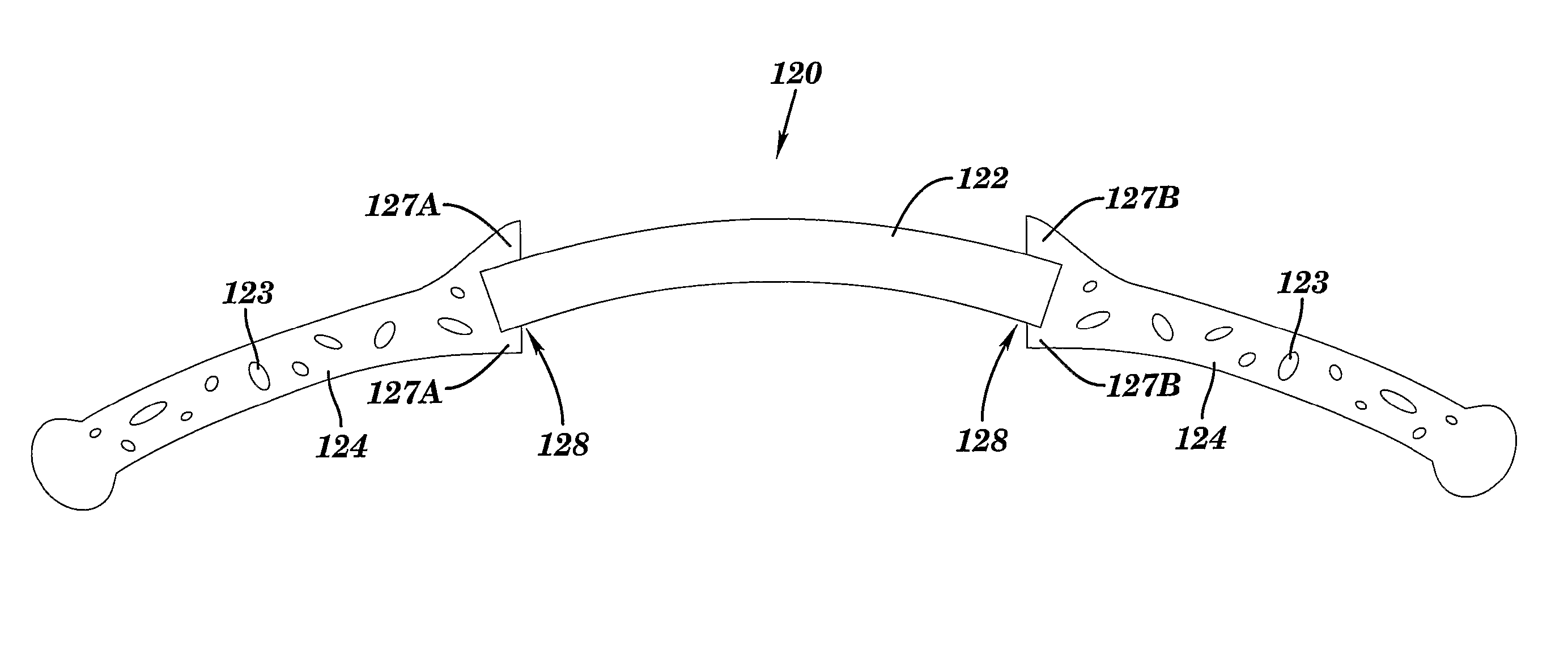
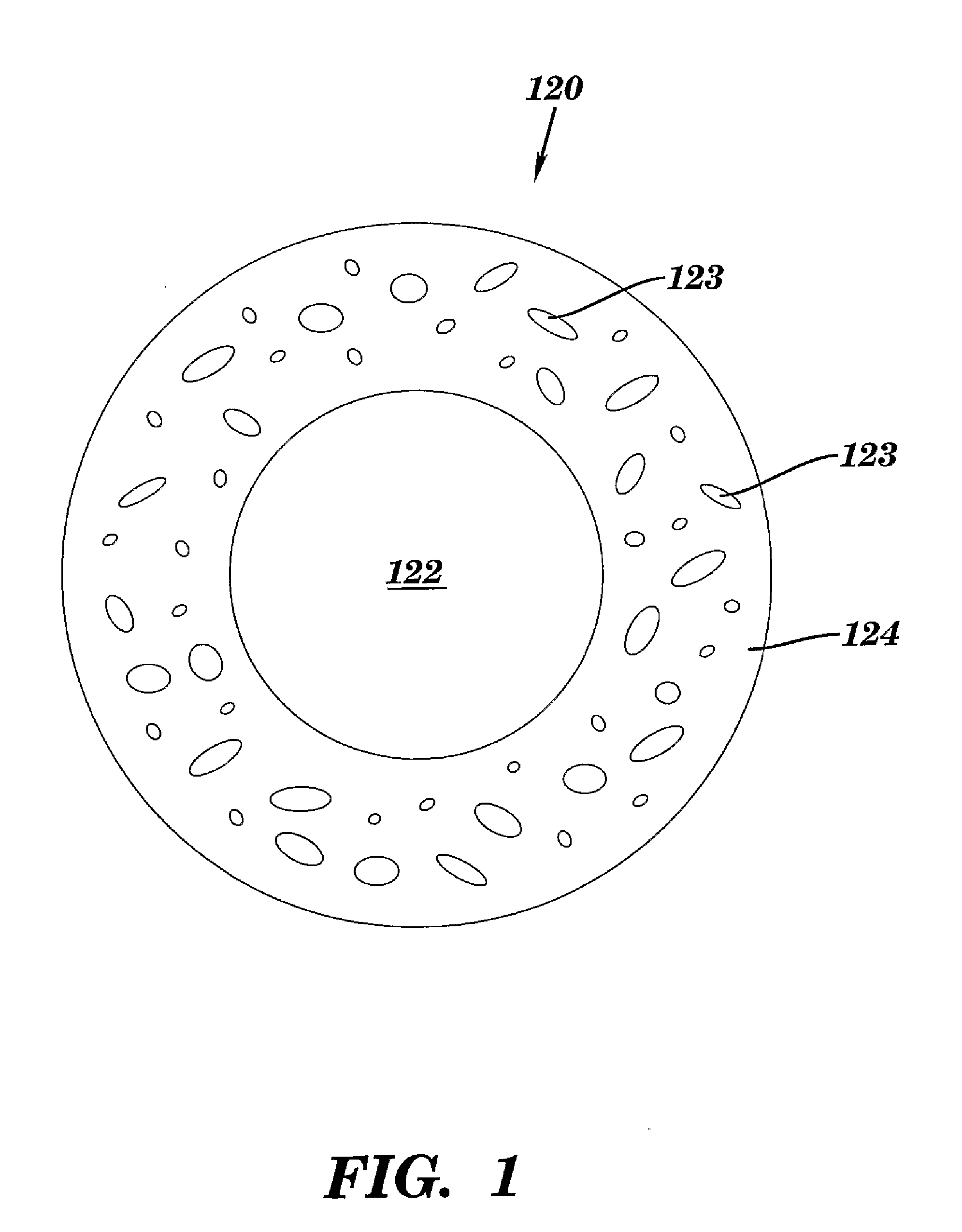
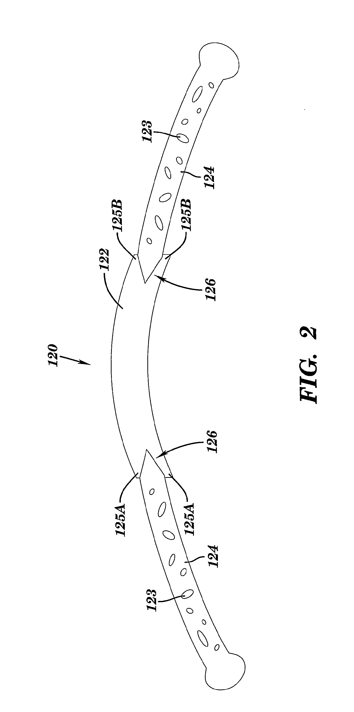
[0053]One aspect of the present invention relates to an intraocular lens having a retainer plate with an annular region surrounding a central opening and an optical lens removably attached to the retainer plate within the central opening.

[0054]FIG. 1 is a plan view of the intraocular lens of the present invention. Intraocular lens 120 has optical lens 122, which is removably attached to retainer plate 124. Either or both of optical lens 122 and retainer plate 124 are constructed of a flexible material including, without limitation, acrylic, silicone, or poly(methylmethacrylate) (“PMMA”), or mixtures thereof. Flexible material allows accommodation of the intraocular lens by flexing with ciliary muscle contraction and vitreous pressure. As a result, intraocular lens 120 has the ability to adjust to surface curvatures. The optical power of a lens or a surface is determined to some extent by the curvature of the surface. An increase or steepening of the curvature (a decrease in the radi...


PUM


Abstract

The present invention relates to an accommodating intraocular lens, which is suitable for replacement of the natural crystalline lens of the eye within the capsular bag. The intraocular lens can include a retainer plate with an annular region surrounding a central opening, and an optical lens. The retainer plate acts as a foundation for the optical lens, as the retainer plate can be positioned near or at the posterior portion of the lens capsule. The optical lens can sit on the retainer plate, but is otherwise not attached to the retainer plate. The optical lens can overlap or fit within the central opening of the retainer plate. The retainer plate can include a lip portion integrally disposed on a region of the retainer plate, wherein the lip provides a surface for holding at least a portion of an intraocular lens.

Description

[0001]This application is a continuation-in-part of co-pending U.S. Non-Provisional patent application Ser. No. 11 / 572,061, filed May 5, 2008 as a national application based on PCT Application No. PCT US05 / 25748, filed Jul. 25, 2005, which claims the priority benefit of U.S. Provisional Patent Application Ser. No. 60 / 590,078, filed Jul. 22, 2004, which are hereby incorporated by reference in their respective entireties.1. FIELD OF INVENTION[0002]Embodiments of the invention relate to intraocular lenses (IOLs) including accommodating IOLs, structures for enhancing the operation of an IOL including accommodating IOLs, methods of implanting intraocular lenses and / or enhancer apparatus into an in-vivo, aphakic eye, and methods of replacing intraocular lenses that have been implanted into a patient's eye.2. BACKGROUND OF INVENTION[0003]Cataracts are currently the leading cause of blindness among adults in the United States. A cataract is a clouding of a part of the eye known as the cryst...

Claims


Application Information

Patent Timeline
Patent Type & Authority Applications(United States)
IPC IPC(8): A61F2/16
CPCA61F2/1635A61F2/1648A61F2250/0024A61F2002/1643A61F2002/164A61F2220/0025A61F2250/006A61F2/15A61F2002/169A61F2/164A61F2/1643
Inventor COLEMAN, D. JACKSON
Owner CORNELL UNIVERSITY
Why Eureka
Try Eureka