Integrated circuit, computer system, and control method

a technology of integrated circuits and control methods, applied in the field of integrated circuits, can solve the problems of wasting processor resources, waste of power, waste of power, etc., and achieve the effect of reducing the amount of power wasted by performing a busy-wait and easy detection of a loop

Inactive Publication Date: 2012-07-12
PANASONIC INTELLECTUAL PROPERTY MANAGEMENT CO LTD
View PDF1 Cites 14 Cited by
  • Summary
  • Abstract
  • Description
  • Claims
  • Application Information

AI Technical Summary

Benefits of technology

[0014]The integrated circuit according to the present invention can detect a loop using the loop detection unit and can distinguish whether the loop is for a busy-wait using the loop-carried dependence analysis unit. Accordingly, the integrated circuit can detect a loop for a busy-wait without comparing the loop with any specific instruction sequence (such as an instruction sequence for an interlock). The integrated circuit can therefore easily detect a loop for a busy-wait formed by an instruction sequence other than specific instruction sequences and perform power saving control during a busy-wait. As a result, a larger variety of busy-waits can be detected, and the amount of power wasted by performing a busy-wait can be reduced.

Problems solved by technology

Busy-waits have the demerit, however, of wasting processor resources.
Therefore, a busy-wait is a wasteful control method from the perspective of power consumption.
This condition is referred to as “spinning” and is a waste of power.

Method used


Image

  • Integrated circuit, computer system, and control method
  • Integrated circuit, computer system, and control method
  • Integrated circuit, computer system, and control method

Examples


embodiment 1

1300>

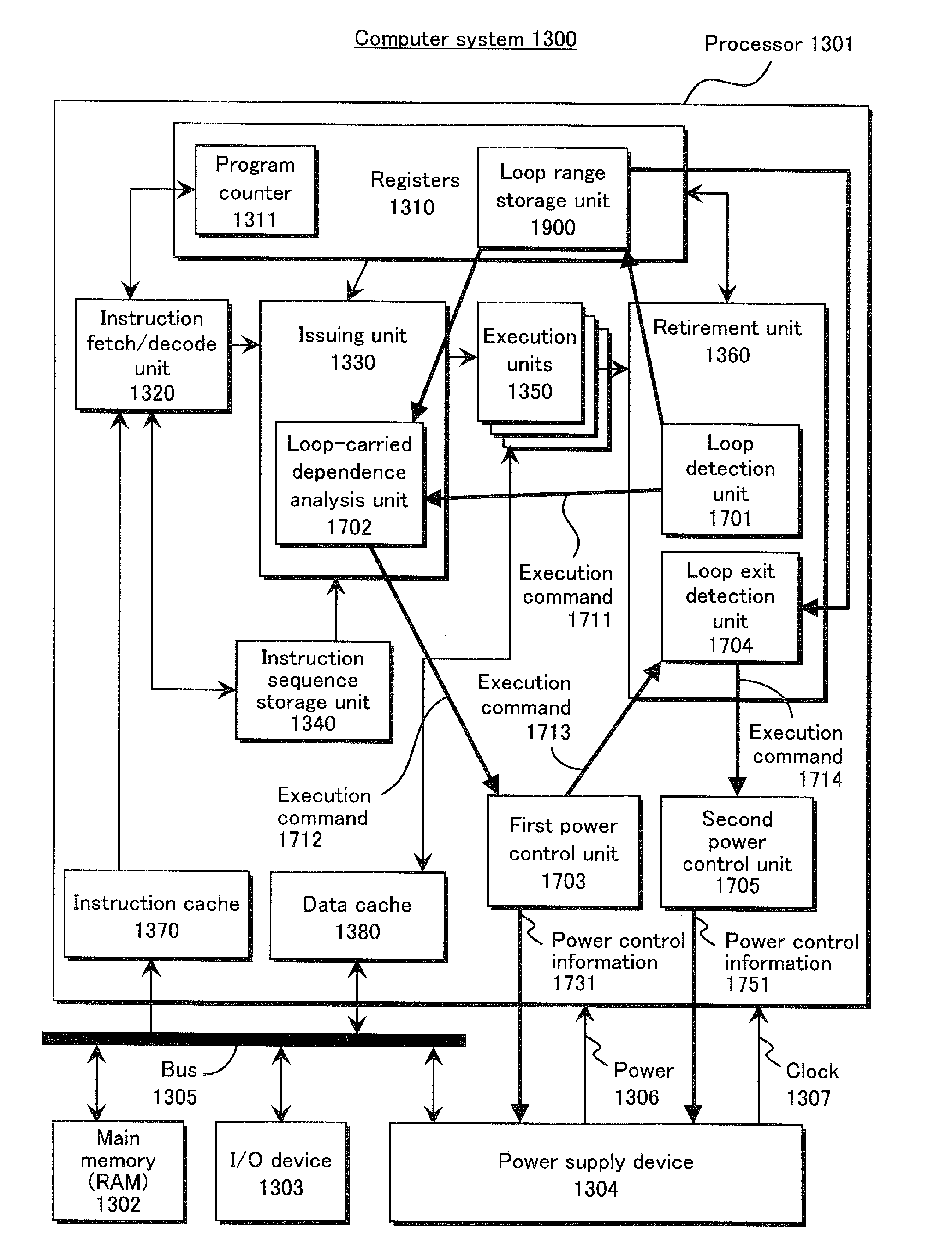
[0050]The structure of a computer system provided with an integrated circuit according to Embodiment 1 of the present invention is described with reference to FIG. 1. FIG. 1 is a block diagram schematically showing the structure of a computer system 1300.

[0051]The computer system 1300 is provided with a processor 1301, a main memory 1302 (RAM, ROM, or the like), an I / O device 1303 (input / output device), a power supply device 1304, and a bus 1305. Note that the processor 1301 is formed within the integrated circuit.

[0052]The processor 1301, the main memory 1302, the I / O device 1303, and the power supply device 1304 are connected to each other by the bus 1305. The power supply device 1304 provides power 1306 and a clock 1307 to the processor 1301.

[0053]The power supply device 1304 is provided with a regulator and can change the voltage of the power 1306 provided to the processor 1301. The power supply device 1304 is also provided with a clock generator and a frequency divider in ...

embodiment 2

[0196]The structure of a computer system 2900 with multithread support in

[0197]Embodiment 2 is now described with reference to FIG. 20.

[0198]In FIG. 20, constituent elements that are the same as the computer system 1300 in FIG. 1 are indicated with the same reference signs, and a description thereof is omitted.

[0199]The computer system 2900 in Embodiment 2 differs from the computer system 1300 in Embodiment 1 in the following points.

[0200](i) The number of registers 2910 in the computer system 2900 equals the number of threads. Each register 2910 is provided with a thread identifier register 2912 and a time slice register 2913.

[0201](ii) The computer system 2900 is provided with a thread switching unit 2920 that switches between threads running in a processor 2901.

[0202](iii) A first power control unit and a second power control unit are provided with a function to output time slice setting information to the registers 2910 and to control the number of execution units 1350 in operat...

embodiment 3

[0287]The structure of a computer system in Embodiment 3 is now described with reference to FIG. 26.

[0288]In FIG. 26, constituent elements that are the same as the computer system 1300 in FIG. 1 are indicated with the same reference signs, and a description thereof is omitted.

[0289]A computer system 4000 in Embodiment 3 differs from the computer system 1300 in Embodiment 1 in the following points.

[0290](i) The computer system 4000 is provided with a program counter monitoring unit 4100 instead of the loop detection unit 1701 and the loop exit detection unit 1704.

[0291](ii) The computer system 4000 is provided with a bus monitoring unit 4200 instead of the loop-carried dependence analysis unit 1702.

[0292]A processor 4020 in an integrated circuit 4010 has the same structure as the processor 1301 in Embodiment 1, excluding the power saving control device (i.e. the loop detection unit 1701, the loop-carried dependence analysis unit 1702, the first power control unit 1703, the loop exit ...


PUM


Abstract

An integrated circuit provided with a processor includes a loop detection unit that detects execution of a loop in the processor, a loop-carried dependence analysis unit that analyzes the loop in order to detect loop-carried dependence, and a power control unit that performs power saving control when no loop-carried dependence is detected. By detecting whether a loop has loop-carried dependence, loops for calculation or the like can be excluded from power saving control. As a result, a larger variety of busy-waits can be detected, and the amount of power wasted by a busy-wait can be reduced.

Description

TECHNICAL FIELD[0001]The present invention relates to an integrated circuit that includes a processor, to a computer system, and to a control method. In particular, the present invention relates to an integrated circuit, a computer system, and a control method for reducing power consumption when a processor performs a busy-wait.BACKGROUND ART [0002]In computer systems with processors, busy-waits are often used when waiting for user input or for synchronization between a plurality of processors (or a plurality of logic processors, processes, threads, or the like) operating in parallel. When a busy-wait is performed, a loop is executed in a processor to repeatedly check, for example, on a specific variable (such as a synchronization variable). Once the value of the specific variable changes to a predetermined value, the loop terminates, and the intended processing is performed.[0003]In the case of a plurality of processors or the like operating in parallel, use of a busy-wait thus all...

Claims


Application Information

Patent Timeline
Patent Type & Authority Applications(United States)
IPC IPC(8): G06F1/32G06F9/38
CPCG06F1/3206G06F1/32
Inventor SUGIYAMA, MASASHISAITO, MASAHIKO
Owner PANASONIC INTELLECTUAL PROPERTY MANAGEMENT CO LTD
Why Eureka
Try Eureka