Hybrid turbocharger system with brake energy revovery

a turbocharger and hybrid technology, applied in the field of modern automotive vehicles, can solve the problems of increasing the battery system adds considerably to the excess of engine exhaust energy at higher engine speeds, so as to achieve the effect of reducing the cost and weight of the vehicle, and reducing the cost of the battery system

Inactive Publication Date: 2012-07-19
KAPICH DAVORIN
View PDF30 Cites 19 Cited by
  • Summary
  • Abstract
  • Description
  • Claims
  • Application Information

AI Technical Summary

Benefits of technology

[0008]Preferred embodiment include a high pressure hydraulic accumulator in hydraulic communication with the hydraulic pump motor and adapted to accumulate high pressure hydraulic fluid pumped by the hydraulic pump motor during vehicle braking cycles and to supply the high pressure fluid back to the hydraulic pump motor during vehicle acceleration cycles to add torque to the drive shaft recovering a portion of vehicle kinetic energy loss during the braking cycles. Applicant estimates that the efficiency of this brake energy recovery will be about the same or better than the brake energy recovery efficiency of electric hybrid vehicles currently on the market, but at much lower cost, much less weight and with much more compact components.

Problems solved by technology

This usually results in an excess of the engine exhaust energy at higher engine speeds.
The problem is the motor-generator and the battery system adds considerably to the cost and weight of the vehicle and occupies substantial space in the vehicle.

Method used


Image

  • Hybrid turbocharger system with brake energy revovery
  • Hybrid turbocharger system with brake energy revovery
  • Hybrid turbocharger system with brake energy revovery

Examples


first preferred embodiments

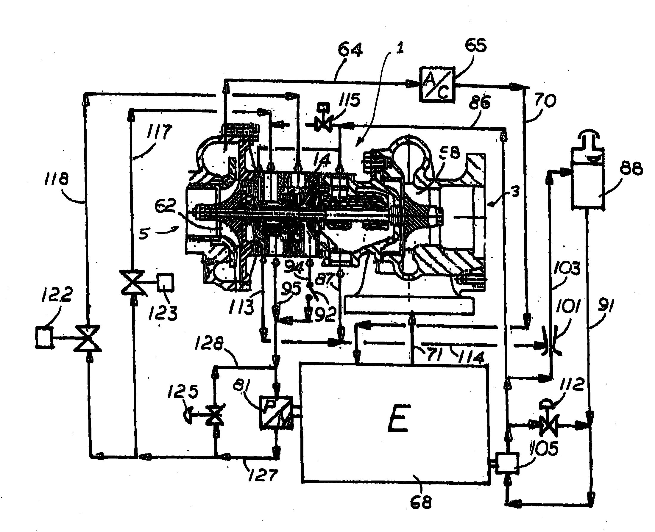
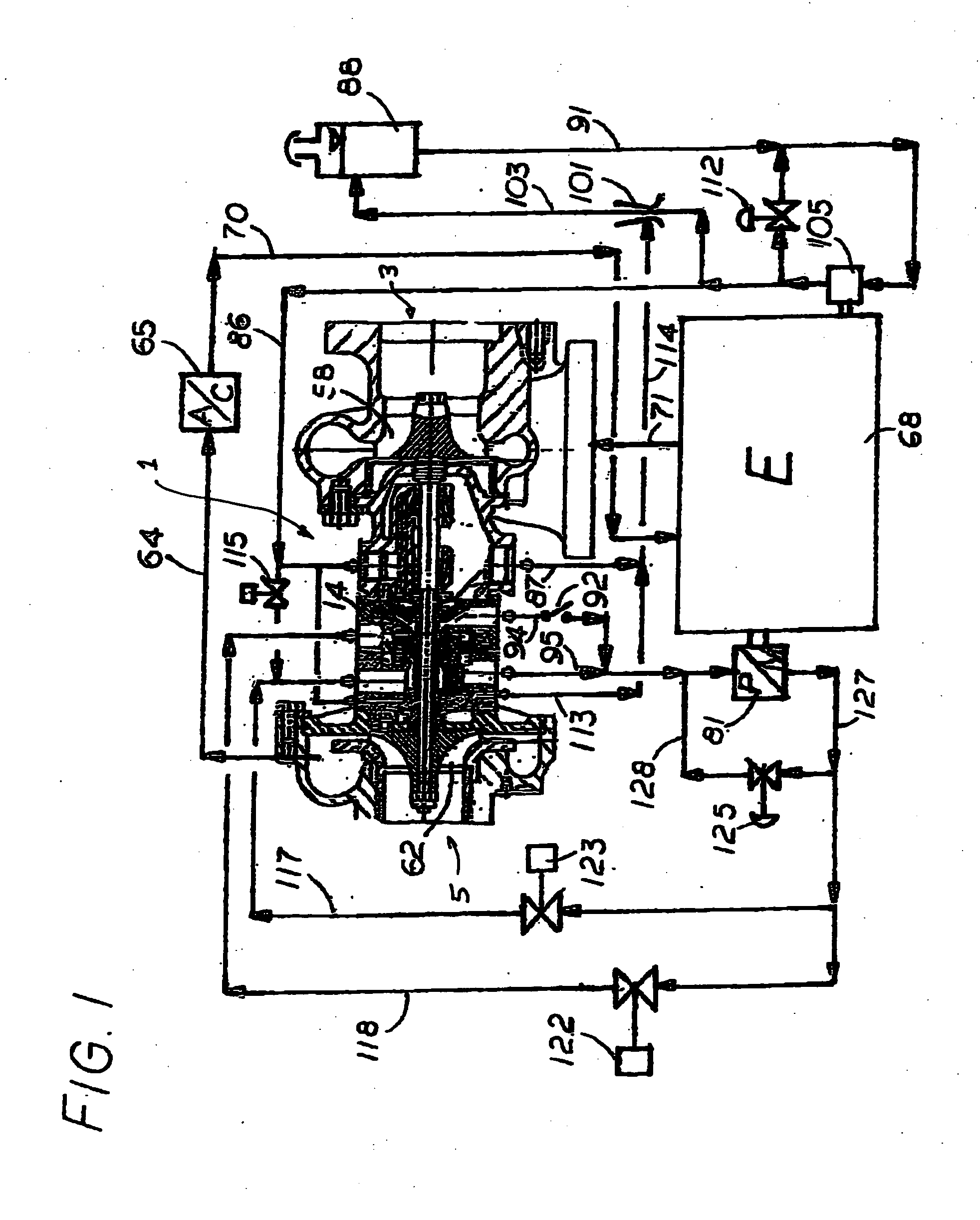
[0016]A first preferred embodiment of the present invention can be described by reference to the figures. FIG. 1 shows some of the important features of the present invention. A hydraulic turbine-pump hybrid turbocharger is shown at 1 in FIG. 1. Turbocharger 1 is driven primarily by engine exhaust line 71 from engine 68. The exhaust gases from the engine are directed through blades 58 of the exhaust gas turbine portion of turbocharger 1. Exhaust gases exit the turbocharger as shown at 3 in FIG. 1. Environmental air is drawn into the compressor portion of turbocharger as shown at 5 and is compressed by compressor blades 62. Compressed air is directed to air cooler 65 via pipe 64 and cooled compressed air is directed into engine 68 via pipe 70. The above portion of the turbocharger is all conventional.

[0017]Constant displacement hydraulic pump motor 81 is passing the hydraulic flow at rate proportional to the engine RPM. With both turbine inlet valve 123 and pump inlet valve 122 close...


PUM


Abstract

A hybrid hydraulic turbocharger system for internal combustion engines. The turbocharger system includes a hydraulic pump motor in mechanical communication with said engine drive shaft. A hybrid turbocharger unit includes an engine exhaust gas turbine driving a compressor, a hydraulic turbine and a hydraulic pump, all mounted on said turbocharger shaft. The hydraulic pump motor functions as a hydraulic pump driven by the drive shaft of the engine to provide additional boost to the turbocharger unit at low engine speeds and functions as a hydraulic motor driven by the turbocharger pump to provide additional torque to the engine drive shaft high engine speeds. Additionally, this system provides for brake energy recovery by storing the energy absorbed during the breaking cycle and releasing it back to the pump motor when required during the subsequent acceleration cycle.

Description

CROSS REFERENCE TO RELATED APPLICATIONS[0001]This application claims the benefit of Provisional Application Ser. No. 61 / 461,564 filed Jan. 20, 2011 and is a continuation in part of Ser. No. 12 / 930,870 filed Jan. 19, 2011.FIELD ON THE INVENTION[0002]The present invention relates to modern automotive vehicles and in particular to systems such as turbocharger systems for improving efficiency and performance.BACKGROUND OF THE INVENTION[0003]Conventional turbochargers use engine exhaust power to drive a turbocharger exhaust turbine which powers an air compressor that supplies high pressure combustion air to the engine. For modern automotive vehicles there is a need for higher specific engine power, lower fuel consumption and lower exhaust emissions. These are met with smaller higher speed engines that require high boost achievable over wide engine speed ranges. A specific need for modern high speed engines is a higher engine torque in the low engine speed range to improve vehicle acceler...

Claims


Application Information

Patent Timeline
Patent Type & Authority Applications(United States)
IPC IPC(8): F02B37/04F02B37/14
CPCF01D25/24F02B37/10F02B37/14F02B39/08Y02T10/144F02C6/12F05B2220/40F05D2220/40F02B41/10Y02T10/12
Inventor KAPICH, DAVORIN
Owner KAPICH DAVORIN
Why Eureka
Try Eureka