Ink jet printing method and device
- Summary
- Abstract
- Description
- Claims
- Application Information
AI Technical Summary
Benefits of technology
Problems solved by technology
Method used
Image
Examples
embodiment 1
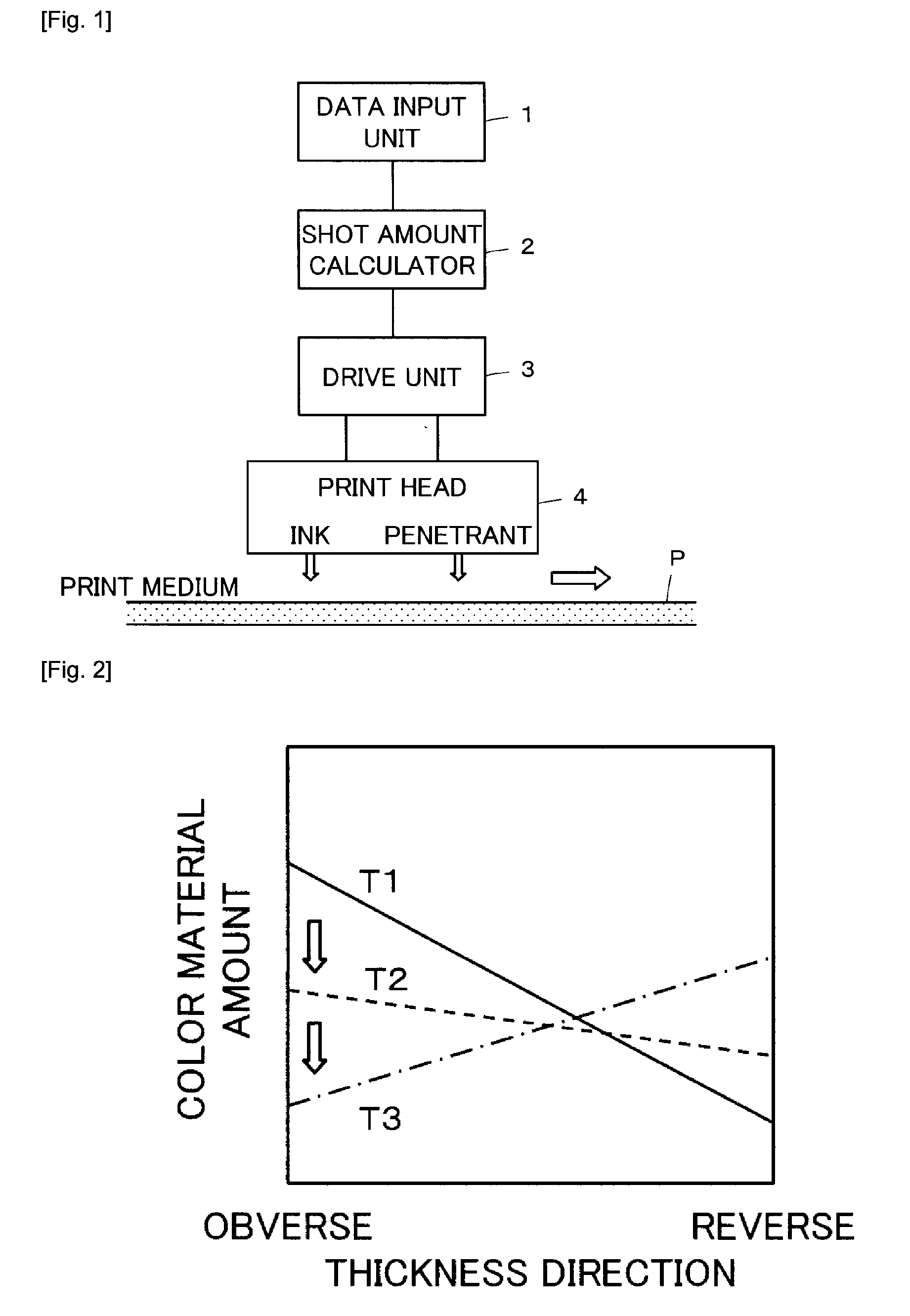
[0037]FIG. 1 illustrates a configuration of an ink jet printing device according to the embodiment 1 of the present invention. The ink jet printing device comprises a data input unit 1, a shot amount calculator 2, a drive unit 3, and a print head 4.
[0038]The data input unit 1 is provided to enter information on a print medium P and information on a print image to be printed on the print medium P designated by an operator. The data input unit 1 may be configured by a keyboard, a mouse, etc.
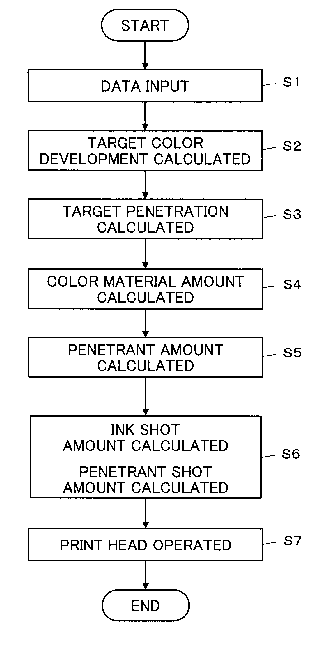
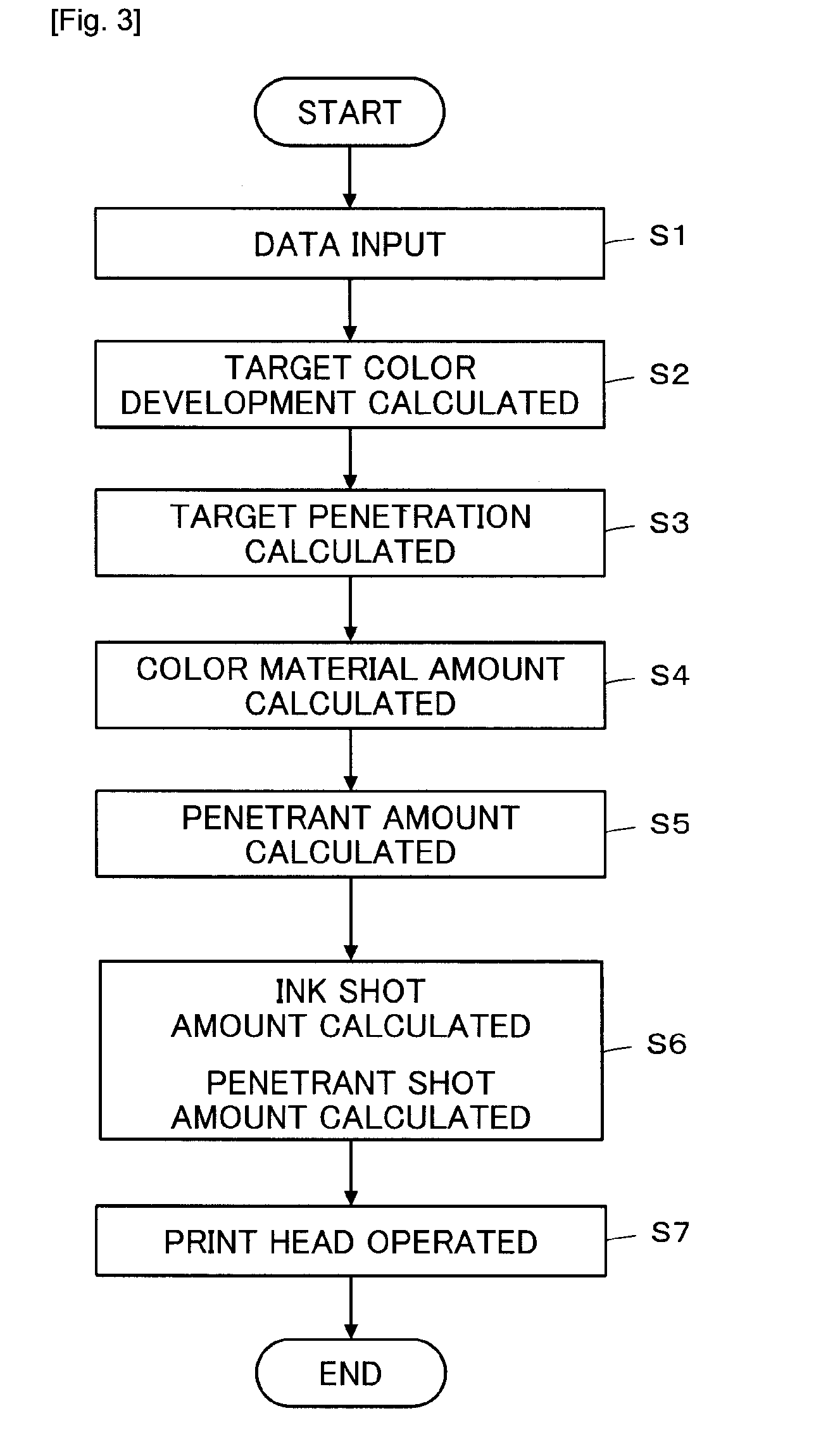
[0039]The data input unit 1 is connected with the shot amount calculator 2. The shot amount calculator 2 calculates amounts of the ink and the penetrant to be shot continuously at each pixel position on the print medium P based on the information on the print medium P and the information on the print image entered through the data input unit 1.
[0040]The information on the print medium P includes color development characteristics resulting from printing a unit color material amount evenly on the pri...
embodiment 2
[0058]FIG. 6 illustrates a configuration of an ink jet printing device according to an embodiment 2. Instead of the print head 4 in the embodiment 1 illustrated in FIG. 1, the ink jet printing device of the embodiment 2 has a first print head 9 and a second print head 10 disposed respectively on the obverse and reverse sides of the print medium P, each equipped with five head units composed of four kinds of ink head units Y, M, C, and K, and a penetrant head unit L. The first print head 9 and the second print head 10 are connected respectively to drive units 11 and 12, which in turn are connected to a shot amount calculator 13. Thus, the ink jet printing device of the embodiment 2 uses the shot amount calculator 13, the drive units 11, 12, and the print heads 9, 10 instead of the shot amount calculator 2, the drive unit 3, and the print head 4 in the ink jet printing device of the embodiment 1 illustrated in FIG. 1.
[0059]As illustrated in FIG. 7, the print medium P is designated and...
embodiment 3
[0075]An ink jet printing device according to an embodiment 3 has the same configuration as the ink jet printing device according to the embodiment 2.
[0076]As with the embodiment 2, the print medium P is designated and a print image is entered through the data input unit 1 for the shot amount calculator 13 to calculate a target color development and a target penetration. In this example, the image uses a color that develops as four colors of ink blend.
[0077]Then, the shot amount calculator 13 calculates color material amounts for achieving a target color development with four colors of ink that are shot sequentially at individual pixel positions on the print medium P based on Kubelka-Munk theory expressed in the formula (1) and the formula (3) above. The shot amount calculator 13 uses the formula (2) above to calculate a variation in color material distribution for achieving the target penetration and a penetrant amount for causing that variation in color material distribution. Then...
PUM
 Abstract
Description
Claims
Application Information
 - R&D
- Intellectual Property
- Life Sciences
- Materials
- Tech Scout
- Unparalleled Data Quality
- Higher Quality Content
- 60% Fewer Hallucinations
Browse by: Latest US Patents, China's latest patents, Technical Efficacy Thesaurus, Application Domain, Technology Topic, Popular Technical Reports.
© 2025 PatSnap. All rights reserved.Legal|Privacy policy|Modern Slavery Act Transparency Statement|Sitemap|About US| Contact US: help@patsnap.com


