Terminal device and retransmission control method

a technology of retransmission control and terminal device, which is applied in the direction of data switching network, frequency-division multiplex, high-level techniques, etc., can solve the problems of terminal difficulty in determining whether or not terminal difficulty in determining whether or not the data is valid, and terminal difficulty in determining whether the control information is valid or not, etc., to achieve the effect of suppressing the increase in the overhead of the uplink control channel

Active Publication Date: 2012-07-19
SUN PATENT TRUST
View PDF3 Cites 26 Cited by
  • Summary
  • Abstract
  • Description
  • Claims
  • Application Information

AI Technical Summary

Benefits of technology

[0047]According to the present invention, a terminal apparatus and a retransmission control method can be provided which are capable of suppressing an increase in the overhead of the uplink contr...

Problems solved by technology

Therefore, the terminal is difficult to decide whether or not the control information is directed to its own terminal until the CRC portion of the received control information is demasked with the terminal ID of the terminal.
However, since each terminal makes a blind decision on a downlink assignment control signal in each subframe directed to its own terminal, the terminal side does not necessarily succeed in receiving the downlink assignment control signal.
Whe...

Method used


Image

  • Terminal device and retransmission control method
  • Terminal device and retransmission control method
  • Terminal device and retransmission control method

Examples


embodiment 1

[0066][Overview of Communication System]

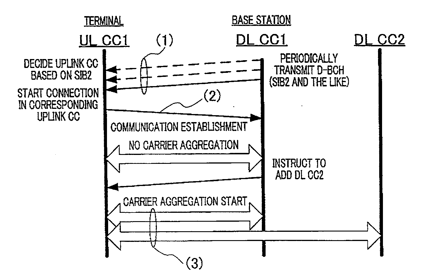
[0067]In a communication system including base station 100 and terminal 200 which will be described later, communication using uplink unit bands and a plurality of downlink unit bands associated with the uplink unit bands is performed, that is, communication based on asymmetric carrier aggregation specific to terminal 200 is performed. This communication system also includes a terminal that does not have a function of performing communication based on carrier aggregation and performs communication by one downlink unit band and one uplink unit band associated with the downlink unit band (that is, communication not based on carrier aggregation), unlike terminal 200.

[0068]Thus, base station 100 is configured to support both communications based on asymmetric carrier aggregation and communication not based on carrier aggregation.

[0069]Communication not based on carrier aggregation may be performed between base station 100 and terminal 200 accordin...

embodiment 2

[0181]In Embodiment 2, the terminal cancels transmission of ACK information in some of downlink unit bands so as to further reduce the overhead of the uplink control channel (PUCCH) compared to Embodiment 1. That is, the terminal drops ACK information in some downlink unit bands. Thus, in Embodiment 2, the overhead of the uplink control channel (PUCCH) can be further reduced compared to Embodiment 1.

[0182]A concrete description will be made below. Basic configurations of the base station and the terminal according to Embodiment 2 are the same as in Embodiment 1, and thus a description will be made with reference to FIG. 6 (base station 100) and FIG. 7 (terminal 200).

[0183][Operation of Terminal 200: When There Are Three Downlink Unit Bands]

[0184]The following description will be made in connection with an example in which three downlink unit bands (downlink unit bands 1, 2, and 3) are set to terminal 200. Here, similarly to Embodiment 1, an ACK / NACK resource (PUCCH resource) associa...


PUM


Abstract

Provided are a terminal device and a retransmission control method that make it possible to minimize increases in overhead in an uplink control channel (PUCCH), even if channel selection is used as the method to transmit response signals during carrier-aggregation communication using a plurality of downlink unit bands. On the basis of the generation status of uplink data and error-detection results obtained by a CRC unit (211), a control unit (208) in the provided terminal (200) uses response signal transmission rules to control the transmission of response signals or uplink control signals that indicate the generation of uplink data. If an uplink control signal and a response signal are generated simultaneously within the same transmission time unit, the control unit (208) changes the resources allocated to the response signal and/or the phase point of the response signal in accordance with the number and position of ACKs within the error-detection result pattern.

Description

TECHNICAL FIELD[0001]The present invention relates to a terminal apparatus and a retransmission control method.[0002]3GPP long term evolution (LTE) adopts orthogonal frequency division multiple access (OFDMA) as a downlink communication scheme. In a radio communication system to which 3GPP LTE is applied, a base station transmits a synchronization signal (synchronization channel: SCH) and a broadcast signal (broadcast channel: BCH) using predetermined communication resources. A terminal first secures synchronization with the base station by catching an SCH. Then, the terminal acquires parameters (e.g. frequency bandwidth) specific to the base station by reading BCH information (see Non-Patent Literatures 1, 2, and 3).[0003]Furthermore, after completing the acquisition of the parameters specific to the base station, the terminal transmits a connection request to the base station and establishes communication with the base station. The base station transmits control information to the...

Claims


Application Information

Patent Timeline
IPC IPC(8): H04L12/24H04L12/26
CPCH04L1/0061H04L1/1854H04W72/0413H04W72/04H04W52/0212H04W28/04H04L1/16H04W72/21H04W76/28Y02D30/70H04L5/0053H04W72/20H04L1/1671H04L1/08
Inventor NAKAO, SEIGONISHIO, AKIHIKOHORIUCHI, AYAKOIMAMURA, DAICHI
Owner SUN PATENT TRUST
Why Eureka
Try Eureka