Virtual Polar Satellite Ground Station for Low Orbit Earth Observation Satellites Based on a Geostationary Satellite Pointing an Antenna Over an Earth Pole

a geostationary satellite and satellite technology, applied in the direction of radio transmission, electrical equipment, transmission, etc., can solve the problems of not being able to exchange tt&c (telemetry, telecommand & control), not being able to download imagery data or sensor data, and not being able to receive tasking commands

Active Publication Date: 2012-07-19
AIRBUS DEFENCE & SPACE
View PDF5 Cites 38 Cited by
  • Summary
  • Abstract
  • Description
  • Claims
  • Application Information

AI Technical Summary

Benefits of technology

[0052]An attractive cost / benefit solution compared to alternative technologies.

Problems solved by technology

It can happen that a LEO satellite is not able to exchange TT&C (Telemetry, Telecommand & Control) or receive tasking commands, or not able to download imagery data or sensor data during several consecutive orbits.
However even with a polar SGS, or a network of SGS the situation is not perfect and faces many problems.
These problems comprise non-technical problems of sovereignty using terrestrial means located in foreign countries.
Further there are problems of congestion.
A further technical problem is that not all orbits are seen by the SGS.
Therefore, a fixed response time cannot be guaranteed.
Furthermore, the main polar SGSs are in the northern hemisphere, it is difficult to establish polar SGS in the southern hemisphere.
As a consequence the southern part of the orbits is not used in an optimal way.
Further it requires a large movement of the antenna to acquire the next EO satellite.
A further problem is that these tracking antennas are generally large and can only be accommodated on rather big and expensive satellites.
However, the models of optical laser terminals that will actually fly in the next coming years are both heavy and expensive, thus limiting the adoption of this technology to low orbit EO satellites with one or more of the following characteristics: large EO satellites, well funded / rich EO satellites programs, EO satellites with needs of transmission of large data files.
Another problem of optical laser technology is the time needed to acquire the line of sight between the geostationary satellite (GEO) and the low orbit EO satellite.
Thus, the communication efficiency of the system is reduced.

Method used


Image

  • Virtual Polar Satellite Ground Station for Low Orbit Earth Observation Satellites Based on a Geostationary Satellite Pointing an Antenna Over an Earth Pole
  • Virtual Polar Satellite Ground Station for Low Orbit Earth Observation Satellites Based on a Geostationary Satellite Pointing an Antenna Over an Earth Pole
  • Virtual Polar Satellite Ground Station for Low Orbit Earth Observation Satellites Based on a Geostationary Satellite Pointing an Antenna Over an Earth Pole

Examples


Embodiment Construction

Satellite Constellation

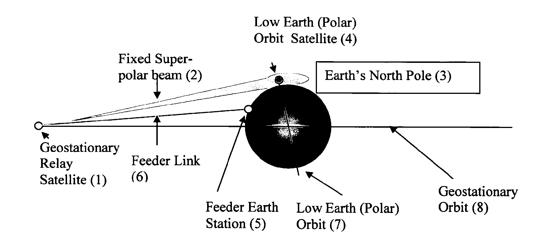
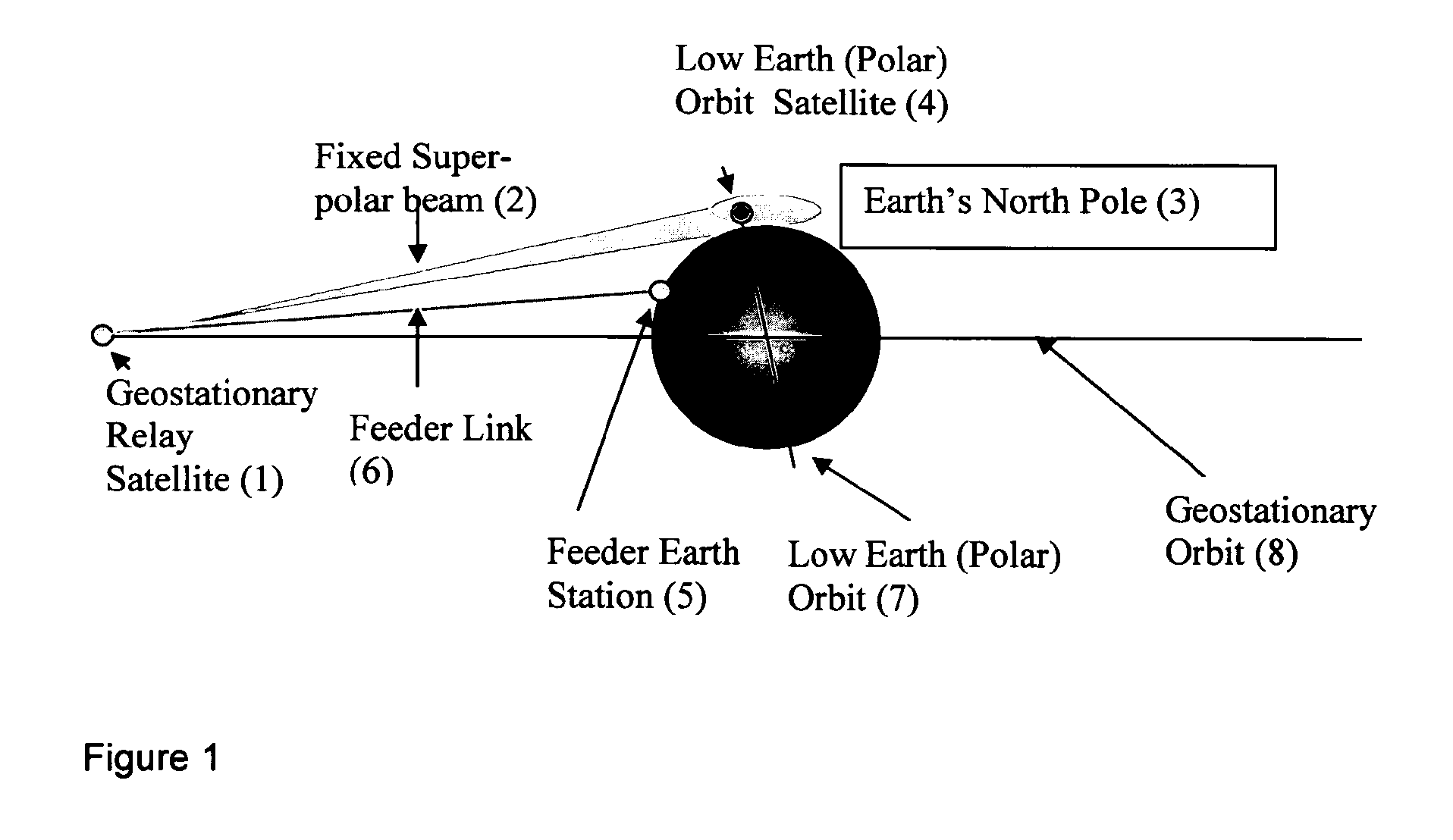
[0066]One embodiment of the invention relates to a satellite constellation. Referring to FIG. 1, the satellite constellation comprises at least one geostationary satellite (1) and at least one low earth orbit satellite (4). The satellite constellation provides communication between a feeder earth station (5) and the low earth orbit satellite (4) even in case that there is no line-of-sight between the feeder earth station (5) and the low earth orbit satellite (4).

[0067]On the geostationary satellite (1) one or more antennas are integrated capable of pointing one at least temporarily one or more fixed super-polar beams (2) to a zone of a super-polar space above the Earth's North Pole (3) (region above the North Pole) through which the orbit (trajectory) of the low earth orbit satellite (4) passes, whereas the one or more fixed super-polar beams (2) cover at least part of the zone.

[0068]The direction of the super-polar beams (2) is fixed at least temporarily with...


PUM


Abstract

A satellite system includes a satellite operating in an orbit around the Earth and a satellite operating in another orbit around the Earth. The satellite points a fixed beam at least temporarily to a zone above the Earth's surface through which the satellite passes.

Description

FIELD OF THE INVENTION[0001]The present invention relates to the communication between a terrestrial Satellite Ground Station (SGS) with one or more polar orbiting Low Earth Orbit (LEO) spacecrafts (e.g. satellites).BACKGROUND OF THE INVENTION[0002]Current SGS cannot see a particular polar orbiting LEO Earth Observation (EO) satellite at each of its orbits around the earth (typically 14 orbits per day). It can happen that a LEO satellite is not able to exchange TT&C (Telemetry, Telecommand & Control) or receive tasking commands, or not able to download imagery data or sensor data during several consecutive orbits.[0003]The number of visibility periods for a given SGS depends on the latitude of the SGS, typically an average of 5 contacts of 10 minutes each per day can be achieved from European latitudes (for example in Toulouse), and up to 10 contacts of 10 minutes each per day for a polar SGS (located for example in Sweden or in Svalbard).[0004]However even with a polar SGS, or a ne...

Claims


Application Information

Patent Timeline
Patent Type & Authority Applications(United States)
IPC IPC(8): H04B7/185
CPCH04B7/18521
Inventor RENOUARD, LAURENTAGNEW, MARTINKINSELLA, FRANCISHEGYI, AKOS
Owner AIRBUS DEFENCE & SPACE
Why Eureka
Try Eureka