Particle filter and method for the purification of an exhaust-gas flow

Inactive Publication Date: 2012-07-26
FORD GLOBAL TECH LLC
View PDF6 Cites 8 Cited by
  • Summary
  • Abstract
  • Description
  • Claims
  • Application Information

AI Technical Summary

Benefits of technology

[0007]The possibility of increasing vehicle emissions may be reduced by providing a secondary exhaust path around a first particulate filter during conditions in which particulate matter stored in a first particulate filter approaches a storage capacity of the first particulate filter. Specifically, during conditions where particulate matter stored in the particulate filter is less than a threshold amount, exhaust gases may be directed substantially solely to the first particulate filter to save or maintain particulate matter storage capacity in a second particulate filter. However, when particulate matter stored in the first particulate filter exceeds the threshold level, a second exhaust pat

Problems solved by technology

In the event of the filter approaching a storage capacity, the increased exhaust-gas counterpressure may have an adverse effect on the performance of the engin

Method used


Image

  • Particle filter and method for the purification of an exhaust-gas flow
  • Particle filter and method for the purification of an exhaust-gas flow
  • Particle filter and method for the purification of an exhaust-gas flow

Examples


Example

[0016]The drawings serve merely for the explanation of the description, and are not intended to restrict the description. The drawings and the individual parts are not necessarily drawn to scale. The same reference numerals are used to denote identical or similar parts.

DETAILED DESCRIPTION

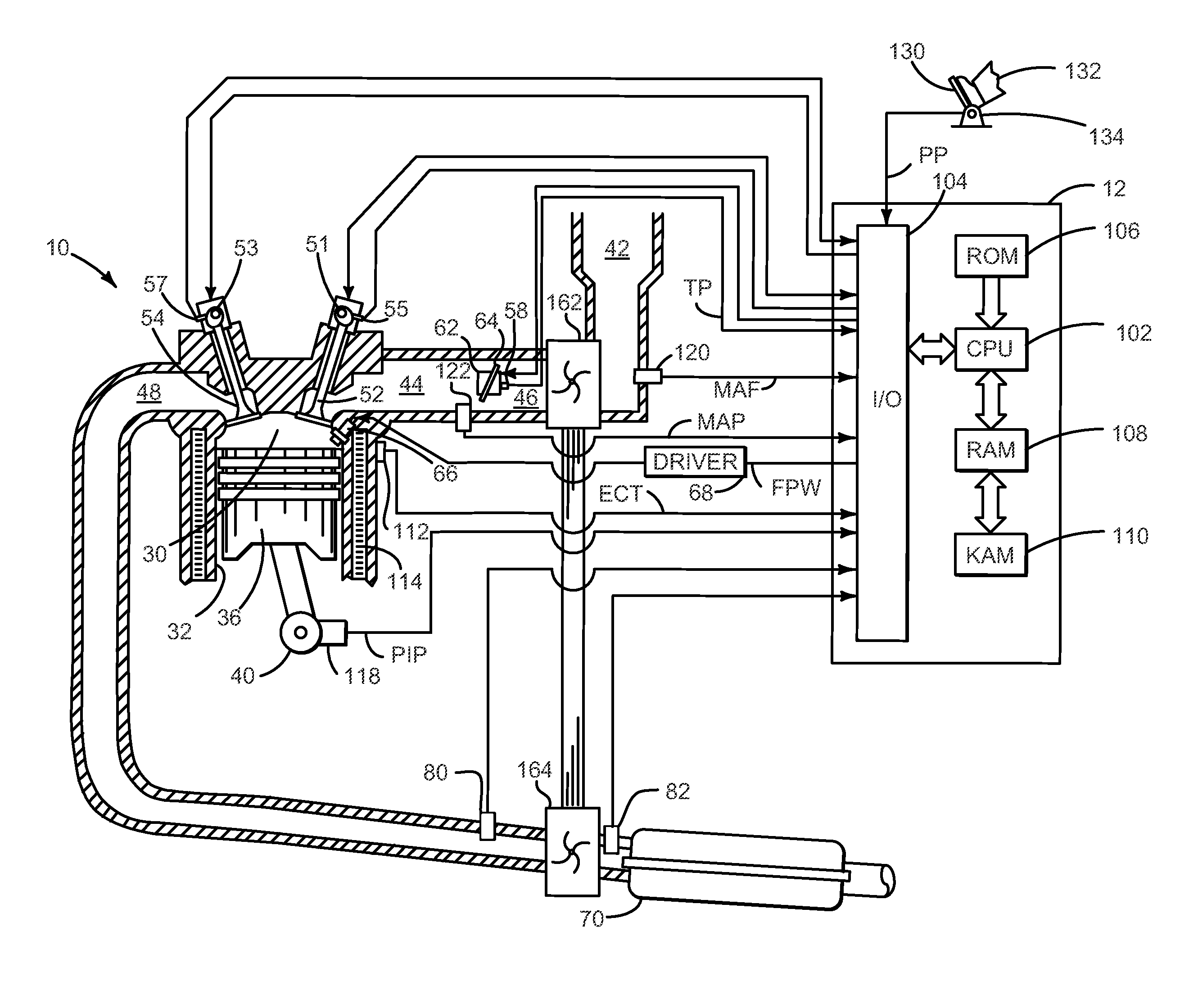
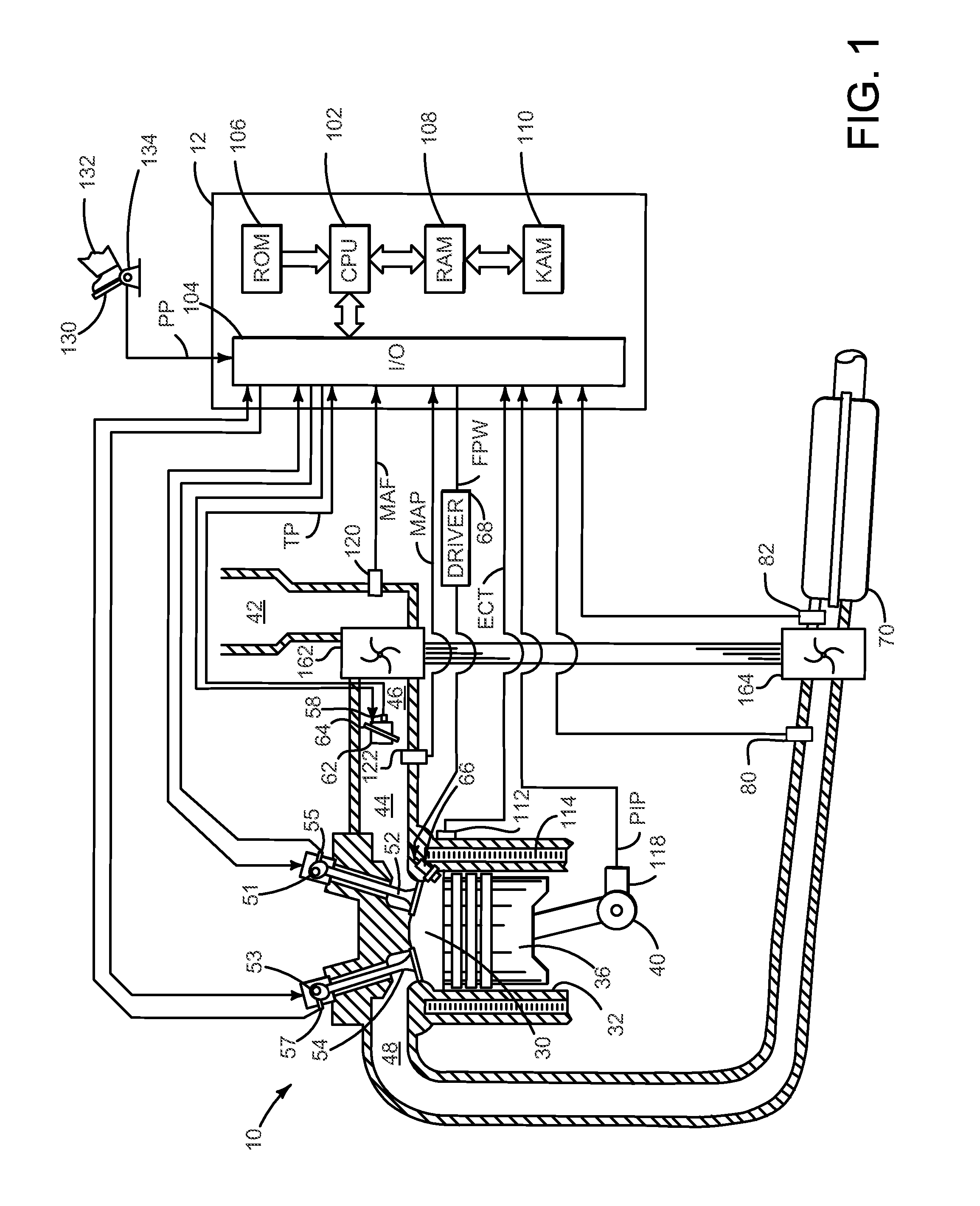
[0017]The present description is related to operating an engine that directs exhaust gas to a particulate filter. In one non-limiting example, the engine may be configured as illustrated in FIG. 1. FIGS. 2 and 3 provide a detailed view of two particulate filters and an exhaust gas routing system that directs exhaust gas through the two particulate filters. Exhaust gases may flow substantially solely through the first particulate filter as is shown in FIG. 2 when particulate matter stored in the first particulate filter is less than a threshold amount. Exhaust gases may flow through the second particulate filter as is shown in FIG. 3 when particulate matter stored in the first particulate filter is ...


PUM


Abstract

Particle filters and a method for the purification of an exhaust-gas flow are described. In one example, exhaust gas is directed solely to a first particulate filter until a predetermined condition. Then exhaust gas is directed to a second particulate filter. One particulate filter may surround the other of two particulate filters. The particulate filters may provide filtered exhaust gas even when one filter becomes at least partially loaded.

Description

RELATED APPLICATIONS[0001]The present application claims priority to German Patent Application No. 102011003019.0 filed on Jan. 24, 2011, the entire contents of which are hereby incorporated by reference for all purposes.FIELD[0002]The description relates to a particle filter and to a method for the purification of an exhaust-gas flow. In particular, the description relates to the purification or filtering of exhaust gases of an internal combustion engine of a motor vehicle.BACKGROUND AND SUMMARY[0003]Particles, such as for example carbonaceous soot, generated during the combustion of fuels may be retained by a filter in order to reduce the exhaust-gas emissions. For this purpose, the exhaust-gas flow passes through a filter in which the particles accumulate. A periodic regeneration of the filter is necessary in order to reduce the particle loading and to ensure a controlled level of the exhaust-gas counterpressure.[0004]In the event of the filter approaching a storage capacity, the...

Claims


Application Information

Patent Timeline
IPC IPC(8): F01N3/18F01N3/02
CPCF01N3/031F01N9/002F01N2560/06F01N13/017F01N2900/1406Y02T10/20Y02T10/47F01N2560/08Y02T10/12Y02T10/40
Inventor YACOUB, YASSER M.
Owner FORD GLOBAL TECH LLC
Why Eureka
Try Eureka