
X-ray tube, irradiation cavity, X-ray source device and application thereof

An X-ray tube and irradiation technology, which is applied in the directions of X-ray tubes, X-ray tube electrodes, X-ray tube parts, etc. The use efficiency of the ray irradiation device, the inapplicability of samples with large dimensions, etc., can achieve the effect of improving the utilization rate of irradiation space, improving the quality of irradiation treatment, and high utilization rate of irradiation space

Pending Publication Date: 2019-02-01
DONGGUAN NEUTRON SCI CENT
View PDF0 Cites 1 Cited by
  • Summary
  • Abstract
  • Description
  • Claims
  • Application Information

AI Technical Summary

Problems solved by technology

Although this kind of X-ray source equipment has quite large dimensions, the effective irradiation space that can actually be used is very limited, which seriously limits the use efficiency of the X-ray irradiation device.
[0006] Moreover, the existing X-ray tubes cannot meet the requirements for higher X-ray intensity applications. At the same time, the uniformity of the X-ray irradiation field generated around it is poor, and the utilization rate of the irradiation space is low, so it is not suitable for large-scale tubes. sample

Method used


Image

  • X-ray tube, irradiation cavity, X-ray source device and application thereof
  • X-ray tube, irradiation cavity, X-ray source device and application thereof
  • X-ray tube, irradiation cavity, X-ray source device and application thereof

Examples


Embodiment 1

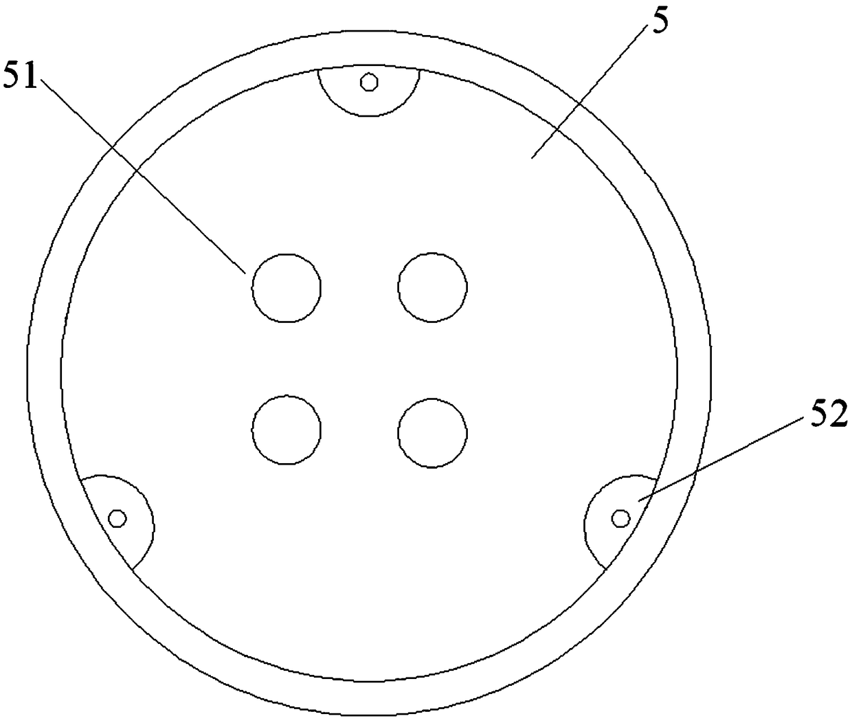
[0047] The irradiation cavity of this example, such as figure 1 As shown, the irradiation cavity is a cylindrical cavity 5, that is, the cross section of the irradiation cavity is circular, and the center of the cylindrical cavity 5 is provided with a sample table 51 for placing irradiated samples; the inner wall of the cylindrical cavity 5 Three X-ray tubes 52 are evenly arranged around the circumference. The X-ray tubes 52 extend along the length of the cylindrical cavity 5 and are parallel to the central axis of the cylindrical cavity 5. That is, the three X-ray tubes 52 are evenly distributed on the circumference of the inner wall of the circular section. In principle, the length of the X-ray tubes is equivalent to the height of the irradiation cavity, or in other words, the height of the irradiation space required by the irradiation cavity.

[0048] In order to make the X-ray tube well fixed on the arc of the inner wall, the X-ray tube adopts a semi-cylindrical structure desi...

Embodiment 2

[0053] The irradiation cavity of this example, such as Figure 4 As shown, the irradiation cavity is a rectangular parallelepiped cavity 6, and the cross-section of the rectangular parallelepiped cavity 6 is square. The center of the rectangular parallelepiped cavity 6 is provided with a sample table 61 for placing the irradiated sample; the inner wall of the rectangular parallelepiped cavity 6 is uniform Four X-ray tubes 62 are arranged, that is, the four X-ray tubes are respectively arranged at four corners of the square. The X-ray tubes 62 extend along the length of the cuboid cavity 6 and are parallel to the central axis of the cuboid cavity 6.

[0054] In order to make the X-ray tube well fixed at the four right-angle positions on the inner wall of the square, the X-ray tube adopts a quarter-cylindrical structure design, that is, the cross-section of the X-ray tube is a quarter-circular structure, such as Figure 5 Shown. This example is different from the first embodiment e...


PUM

PropertyMeasurementUnit
Thicknessaaaaaaaaaa

Abstract

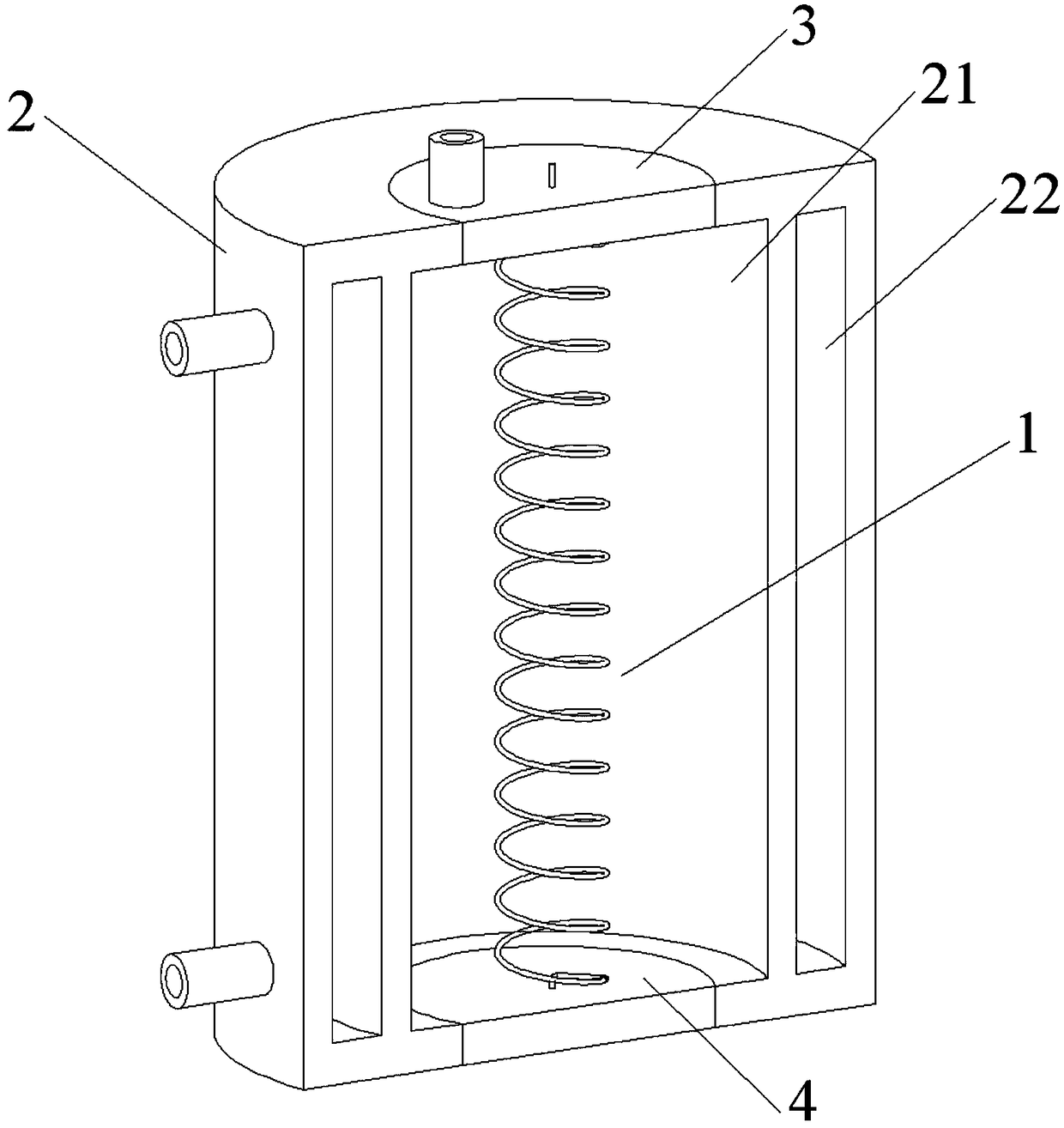
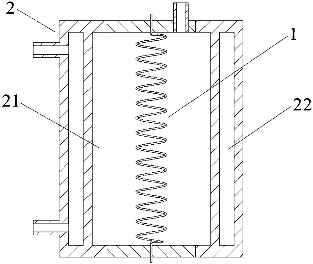
The present invention discloses an X-ray tube, an irradiation cavity, an X-ray source device and an application thereof. The X-ray tube comprises a cathode filament, a housing, a cover plate and a bottom plate; the internal portion of the housing is a column-shaped vacuum chamber, and two ends of the column-shaped vacuum chamber are respectively sealed by the cover plate and the bottom plate; thecathode filament is winded to a structure being similar to a spring in a heliciform form, the cathode filament is installed in the column-shaped vacuum chamber and is arranged in the length directionof the column-shaped vacuum chamber, the two ends of the cathode filament, namely the two ends of the spring structure, respectively pass through the cover plate and the bottom plate to connect with apower source; and the inner wall of the column-shaped vacuum chamber is uniformly coated with a heavy metal coating as an anode. The X-ray tube is optimized and improved in structure, is large in irradiation space and irradiation intensity, and is especially suitable for application occasions with large irradiation intensities. The new X-ray tube with improved performances is provided for variousX-ray source devices so as to greatly improve the irradiation space utilization rate and the irradiation processing quality of the X-ray source device.

Description

Technical field [0001] This application relates to the field of irradiation devices, in particular to an X-ray tube, irradiation cavity, X-ray source equipment and applications. Background technique [0002] Biological irradiation is to irradiate organisms with high-energy rays with ionizing radiation effects within a predetermined period of time, so that the irradiated organisms produce biological cell chromosomal mutations and gene mutations, thereby changing or affecting the organism’s traits and metabolic processes And genetic characteristics. Biological irradiation technology has made great achievements in the fields of medical treatment, sterilization and antivirus, food preservation, mutation breeding of agricultural and animal husbandry products, pest and infectious disease vector sterility control (SIT). [0003] There are two main types of commonly used biological irradiation equipment, namely gamma source equipment and X-ray source equipment. Gamma source equipment usu...

Claims


Application Information

Patent Timeline
IPC IPC(8): H01J35/06H01J35/16
CPCH01J35/06H01J35/16H01J2235/06H01J2235/163
Inventor 胡春明杜文婷
Owner DONGGUAN NEUTRON SCI CENT
Learn More