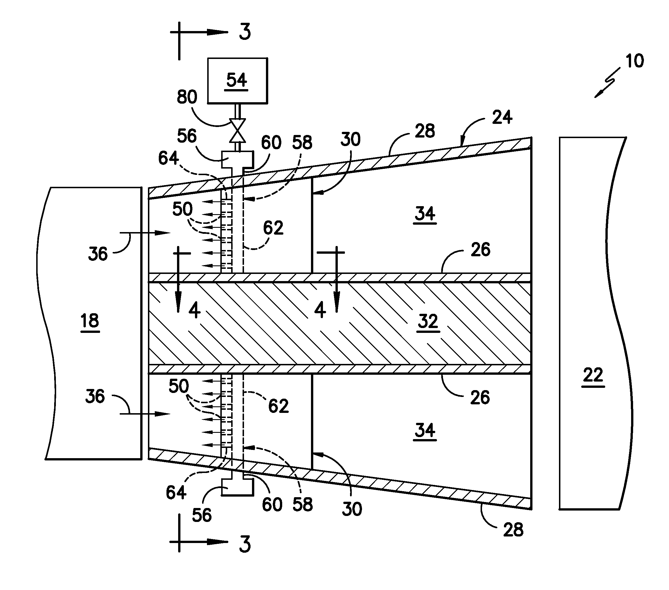
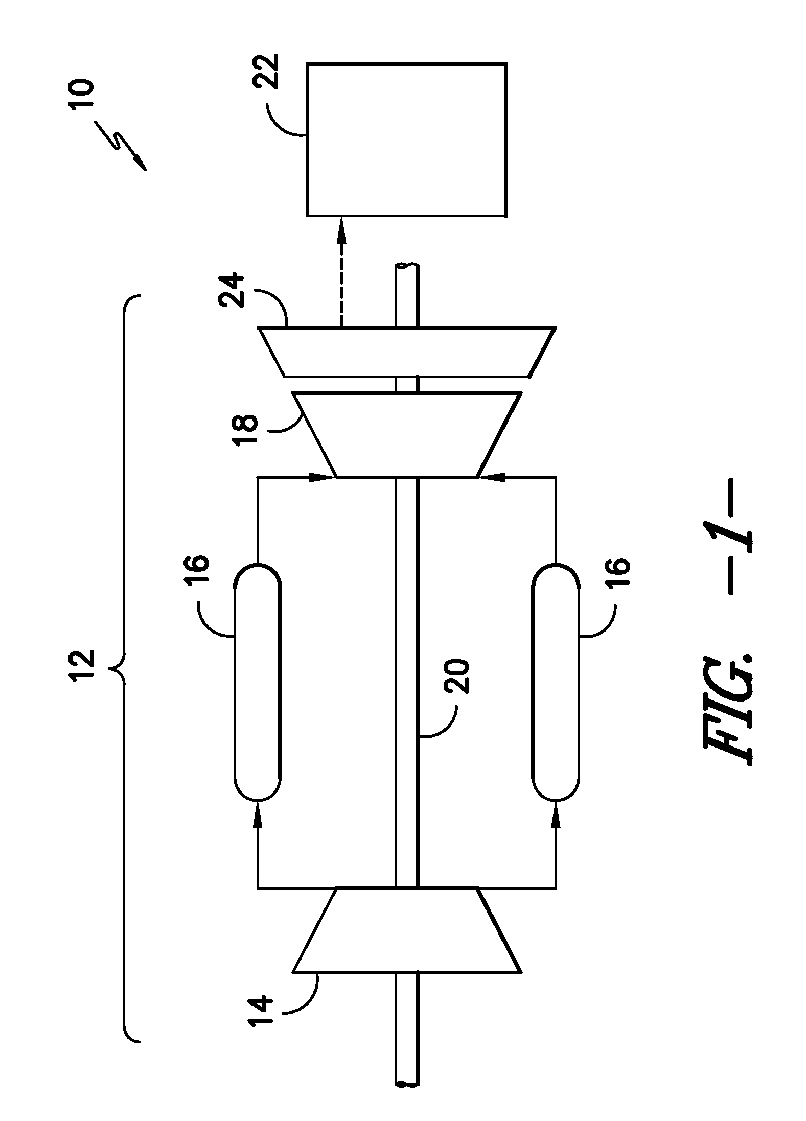
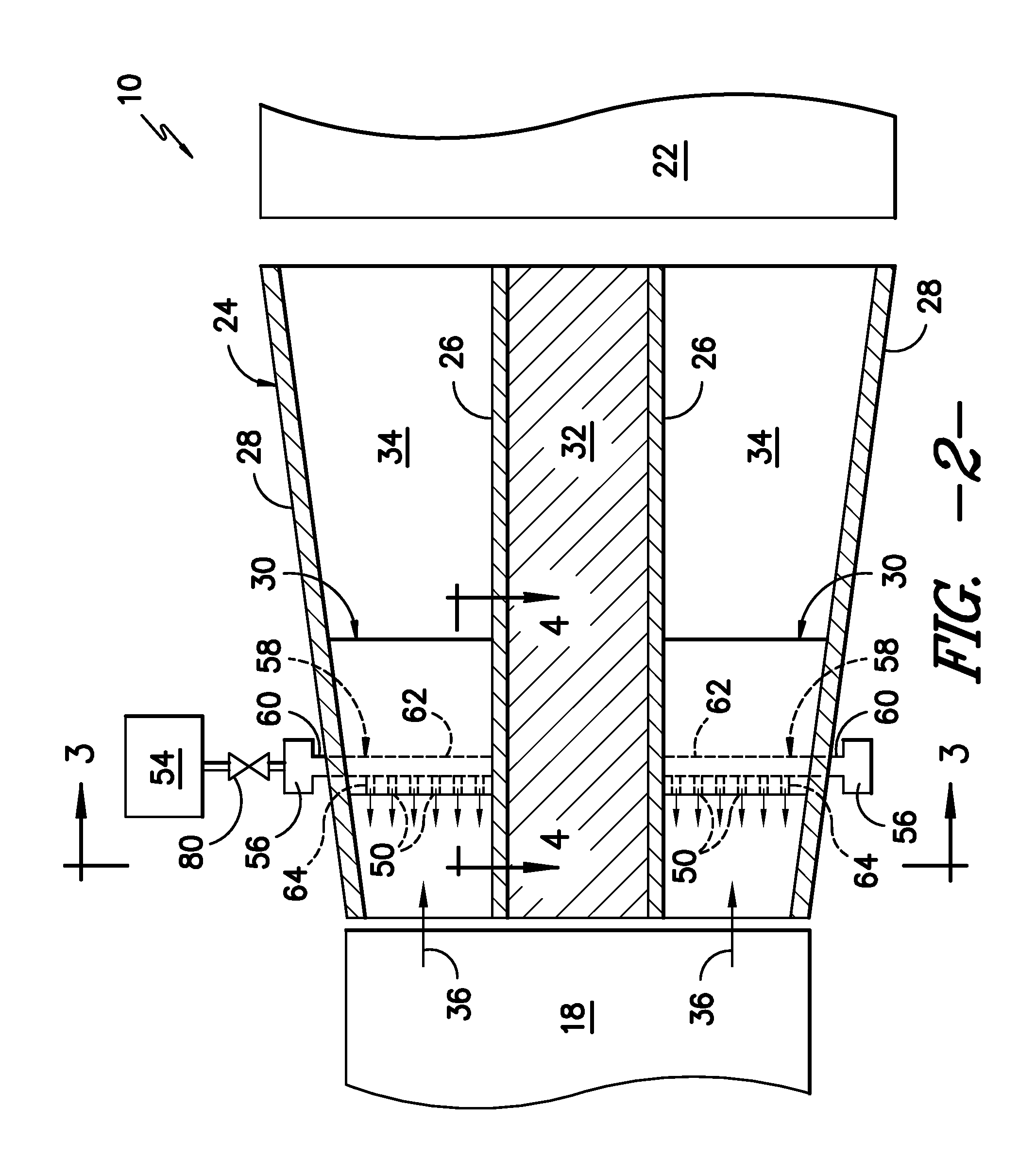
System and method for a gas turbine exhaust diffuser
a technology of exhaust diffuser and gas turbine, which is applied in the direction of hot gas positive displacement engine plants, engine components, machines/engines, etc., can solve the problems of limited turndown capability of gas turbines, increased exhaust temperatures, and difficulty in determining how and to what extent to adjust combustor operation
- Summary
- Abstract
- Description
- Claims
- Application Information
AI Technical Summary
Benefits of technology
Problems solved by technology
Method used
Image

Examples
Embodiment Construction
[0020]Reference now will be made in detail to embodiments of the invention, one or more examples of which are illustrated in the drawings. Each example is provided by way of explanation of the invention, not limitation of the invention. In fact, it will be apparent to those skilled in the art that various modifications and variations can be made in the present invention without departing from the scope or spirit of the invention. For instance, features illustrated or described as part of one embodiment can be used with another embodiment to yield a still further embodiment. Thus, it is intended that the present invention covers such modifications and variations as come within the scope of the appended claims and their equivalents.
[0021]In general, the present subject matter is directed to a system and method for reducing the temperature of the exhaust gases exiting the gas turbine and flowing to downstream components, such as the heat recovery steam generation (HRSG) system of a com...
PUM
 Abstract
Description
Claims
Application Information