

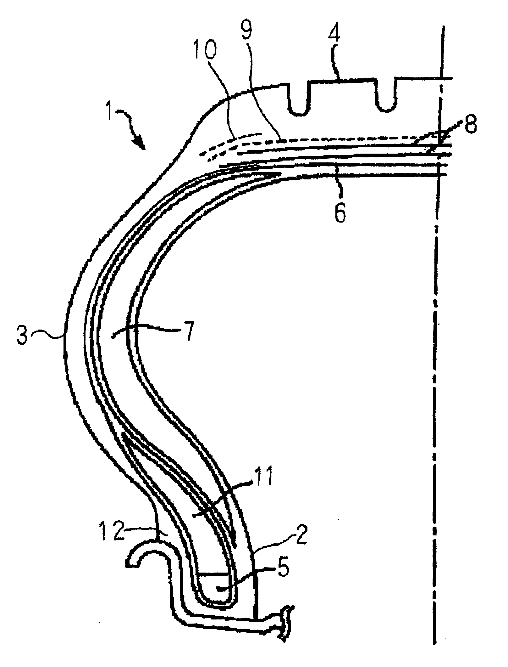
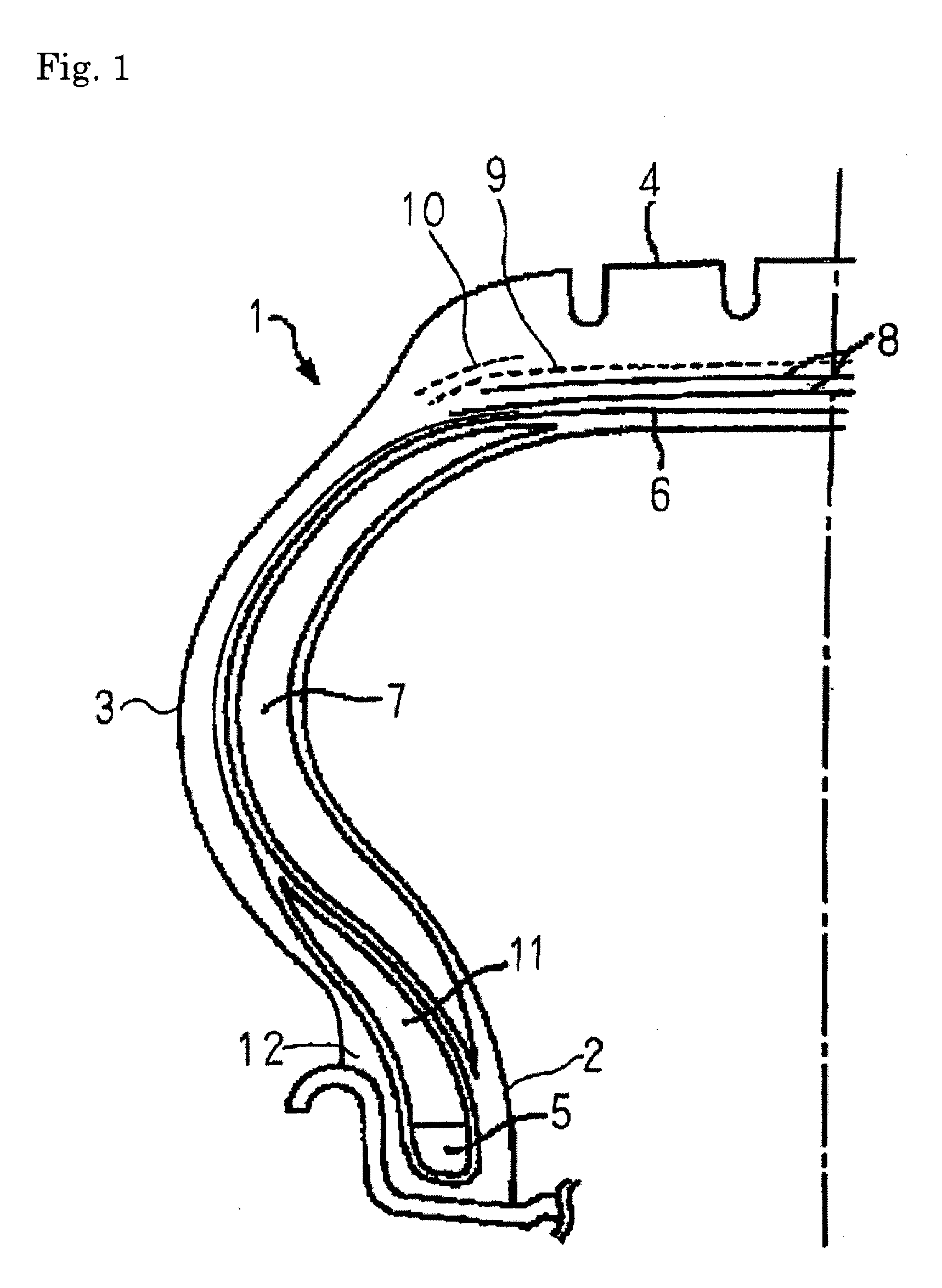
Pneumatic safety tire
a safety tire and pneumatic technology, applied in the field of pneumatic safety tires, can solve the problems of increasing weight and the cost of tires, unable to improve durability sufficiently, and generating heat in rubber, so as to reduce the deformation of the tread portion, improve the performance of run flats, and reduce the effect of buckling
- Summary
- Abstract
- Description
- Claims
- Application Information
AI Technical Summary
Benefits of technology
Problems solved by technology
Method used
Image

Examples
examples
[0085]The present invention will be described more specifically with reference to examples in the following. However, the present invention is not limited to the examples. Various measurements were conducted in accordance with the following methods.
1. Tensile Strength and Tensile Modulus
[0086]The tensile strength and the tensile modulus were measured in accordance with the methods of Japanese Industrial Standard L-1013. As the tensile modulus, the initial modulus calculated based on the stress at an elongation of 0.1% and the stress at an elongation of 0.2% was used.
2. Degree of Dry Thermal Contraction
[0087]The dry heat treatment was conducted in an oven at 150° C. for 30 minutes. The length of a fiber was measured under a load of 1 / 30 (cN / dtex) before and after the heat treatment, and the degree of dry thermal contraction was obtained in accordance with the following equation:
Degree of dry thermal contraction (%)=(Lb−La) / Lb×100
wherein Lb represents the length of the fiber before th...
examples 1 to 3
[0099]A fiber cord of the polyketone (1670 dtex / 2) exhibiting a maximum stress of thermal contraction of 0.91 cN / dtex was applied to the first belt reinforcing layer, and a fiber cord of rayon (1840 dtex / 3) was applied to the carcass.
example 4 to 6
[0100]A fiber cord of the polyketone (1100 dtex / 2) exhibiting a maximum stress of thermal contraction of 0.93 cN / dtex was applied to the first belt reinforcing layer, and a fiber cord of the polyketone (1670 dtex / 2) exhibiting a maximum stress of thermal contraction of 0.91 cN / dtex was applied to the carcass.
PUM
| Property | Measurement | Unit |
|---|---|---|
| width | aaaaa | aaaaa |
| temperature | aaaaa | aaaaa |
| stress of thermal contraction | aaaaa | aaaaa |
Abstract
Description
Claims
Application Information