

Electric power steering device and assembly method thereof
A technology of power steering and assembly method, applied in electric steering mechanism, power steering mechanism, transmission device, etc., can solve the problems of increasing cost and needing special purpose, and achieve the effects of reducing vibration, preventing buckling deformation, and improving detection sensitivity
- Summary
- Abstract
- Description
- Claims
- Application Information
AI Technical Summary
Problems solved by technology
Method used
Image

Examples
no. 1 Embodiment approach
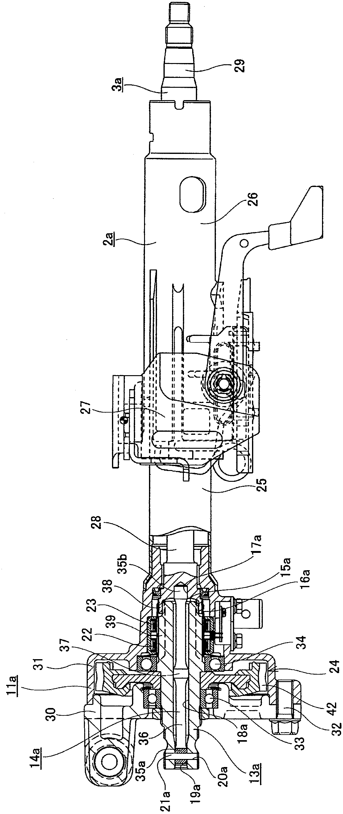
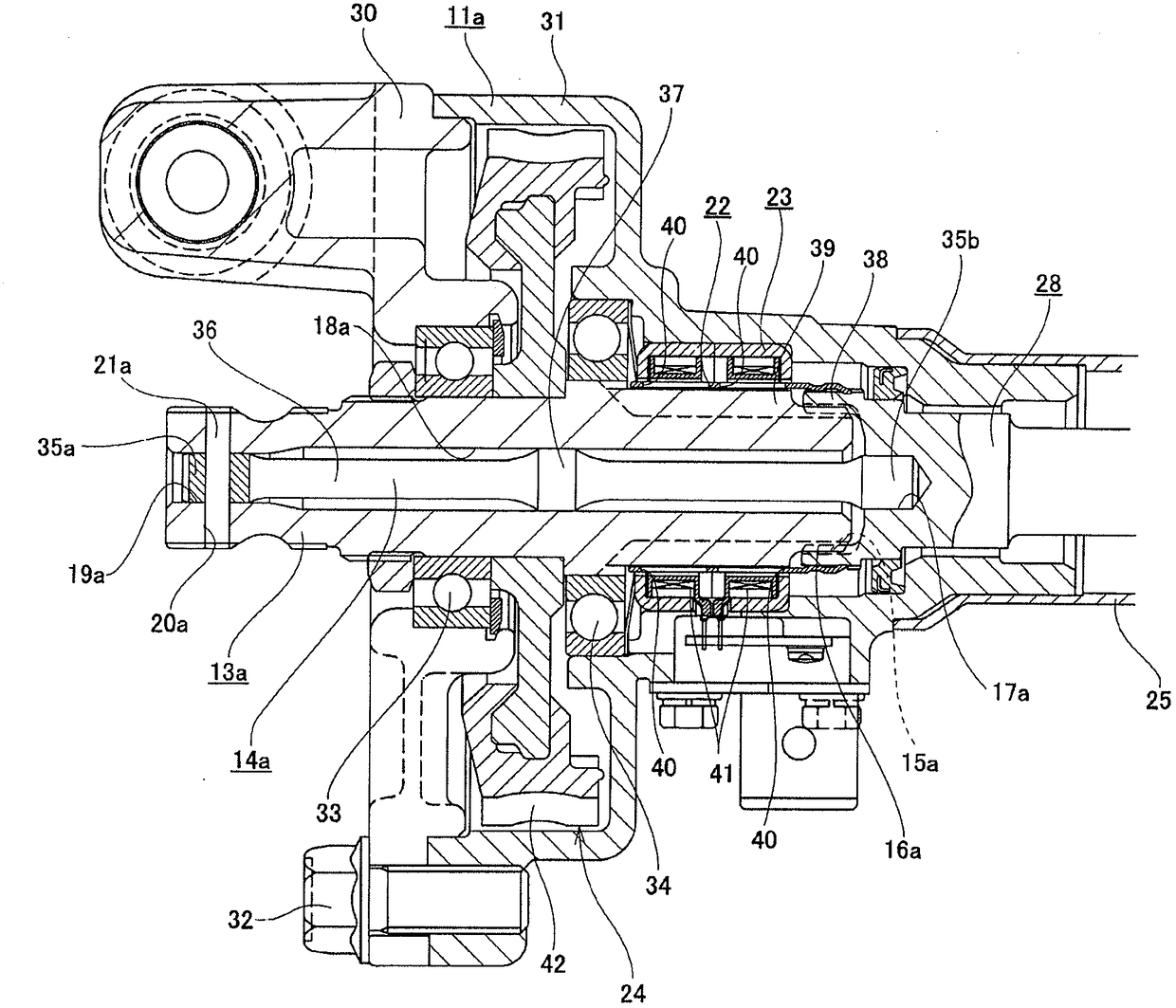
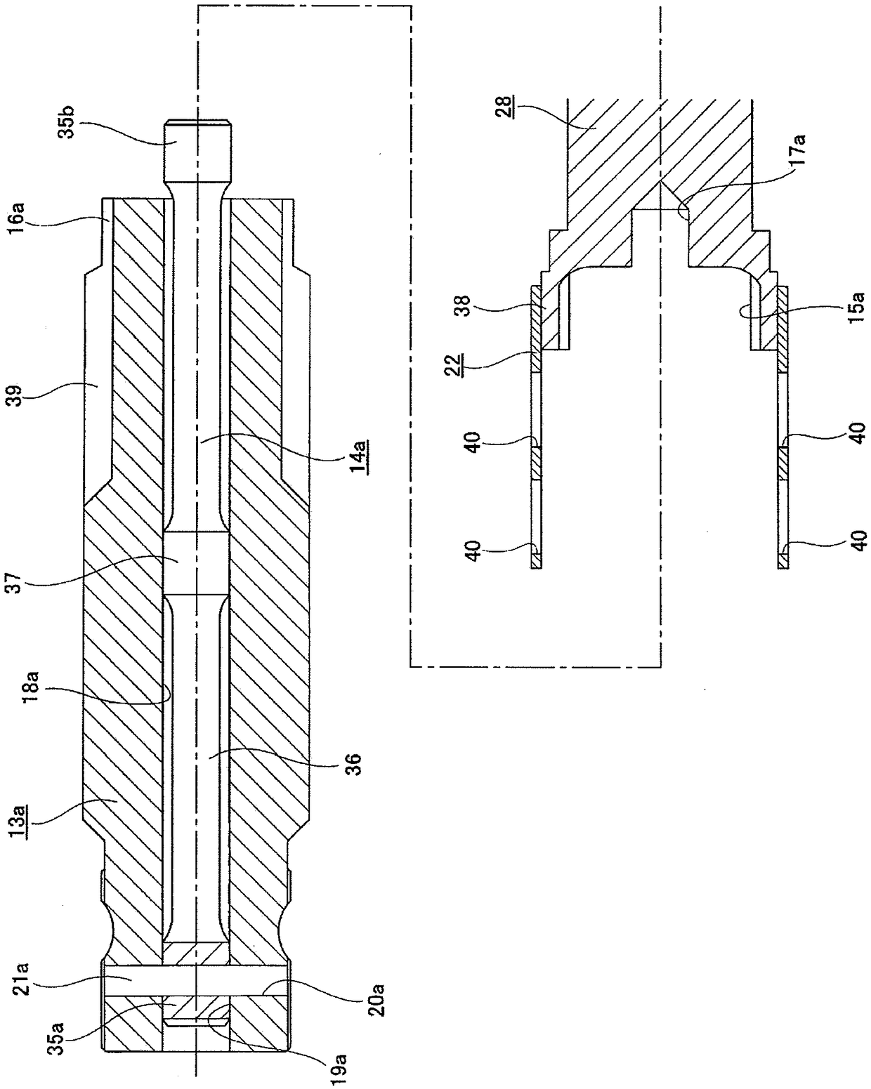
[0128] refer to Figure 1~5 The first embodiment of the present invention will be described. In addition, in Figure 1~5 In the middle, the left side is the front side, and the right side is the back side. The electric power steering apparatus of this embodiment includes a steering column 2a, a steering shaft 3a, a housing 11a, an output shaft 13a, a torsion bar 14a, a bush 22 for torque detection, a coil unit 23 for torque detection, and an electric motor 10 (see Figure 21 ), and the worm gear reducer 24.
[0129] The steering column 2 a is formed by telescopically combining a cylindrical inner column 25 arranged on the front side and a cylindrical outer column 26 arranged on the rear side, and is supported on the vehicle body by a support bracket 27 . The inner column 25 and the outer column 26 are made of light alloy such as steel or aluminum alloy.
[0130] The steering shaft 3a is formed by spline-fitting a hollow shaft-shaped upper shaft 29 disposed on the rear side ...
no. 2 Embodiment approach
[0154] refer to Figure 6-8 A second embodiment of the present invention will be described. In addition, in Figure 6-8 In the middle, the left side is the front side, and the right side is the back side.
[0155] In the case of this embodiment, if Figure 8 As shown, the structure for coupling the front coupling shaft portion 35c of the torsion bar 14b to the output shaft 13b so that torque can be transmitted is different from that of the first embodiment described above. That is, in the case of the present embodiment, in order to connect the connecting shaft portion 35c to the output shaft 13b so that the torque can be transmitted, the connecting shaft portion 35c is press-fitted into the connecting hole provided at the front end portion of the central hole 18b of the output shaft 13b. 19b. As a result, the male serrations provided on the outer peripheral surface of the connecting shaft portion 35c and subjected to hardening treatment such as quenching are mechanically b...
no. 3 Embodiment approach
[0164] Figure 9 The third embodiment of the present invention is shown. In this embodiment, the number and axial position of the large-diameter portions provided in the axially intermediate portion of the spring shaft portion 36a constituting the torsion bar 14c are different from those in the second embodiment described above. That is, in the case of the present embodiment, a pair of large-diameter portions 37 , 37 are provided at portions near both ends of the axially intermediate portion of the spring shaft portion 36 a. Furthermore, the cylindrical outer peripheral surface of the large-diameter part 37,37 and the cylindrical inner peripheral surface of the output shaft 13b are brought into contact with the cylindrical inner peripheral surface close to or without interference. In this way, in the case of this embodiment, since a pair of large-diameter portions 37, 37 are provided near both ends of the axially intermediate portion of the spring shaft portion 36a, based on th...
PUM
 Abstract
Description
Claims
Application Information