Radiation Shielding Lid For An Auxiliary Shield Assembly of A Radioisoptope Elution System

a technology of radioisotope elution system and shielding lid, which is applied in shielding, nuclear engineering, nuclear elements, etc., can solve the problems of system operation less effective, system failure, and/or total uselessness, and achieve the effect of convenient gripping of the vial

Active Publication Date: 2012-07-26
CURIUM US LLC
View PDF4 Cites 12 Cited by
  • Summary
  • Abstract
  • Description
  • Claims
  • Application Information

AI Technical Summary

Benefits of technology

[0007]One aspect of this disclosure relates to a radiation shielding lid for a radiation shielding container that includes a body having an upper surface and an opposing lower surface. A vial opening is defined in the body of the lid. This vial opening has a lower end found at the lower surface of the body and an upper end intermediate the upper and lower surfaces of the body. A finger recess is defined in the upper surface of the body and is sized and shaped to allow at least a distal portion of each of at least two digits (e.g., thumb/fingers of a technician) to enter the finger recess. This finger recess has an upper edge adjacent the upper surface of the body and a lower edge adjacent the upper end of the vial opening. First and second wings extend upward from adjacent the upper end of the vial opening. Each of these first and second wings has opposite sides, a top portion, and an inner surface extending partially around

Problems solved by technology

Although this type of system generally tends to work well, one problem associated with this type of system is that the input connector and/or output connector of the generator—particularly where the input and output connectors are hollow needles—may be bent, crushed, or broken due to misalignment of the eluant vial and/or the elution vial with the respective input and/or output connectors when making the fluid connection(s).
As a result of the broken or deformed needles

Method used


Image

  • Radiation Shielding Lid For An Auxiliary Shield Assembly of A Radioisoptope Elution System
  • Radiation Shielding Lid For An Auxiliary Shield Assembly of A Radioisoptope Elution System
  • Radiation Shielding Lid For An Auxiliary Shield Assembly of A Radioisoptope Elution System

Examples


Embodiment Construction

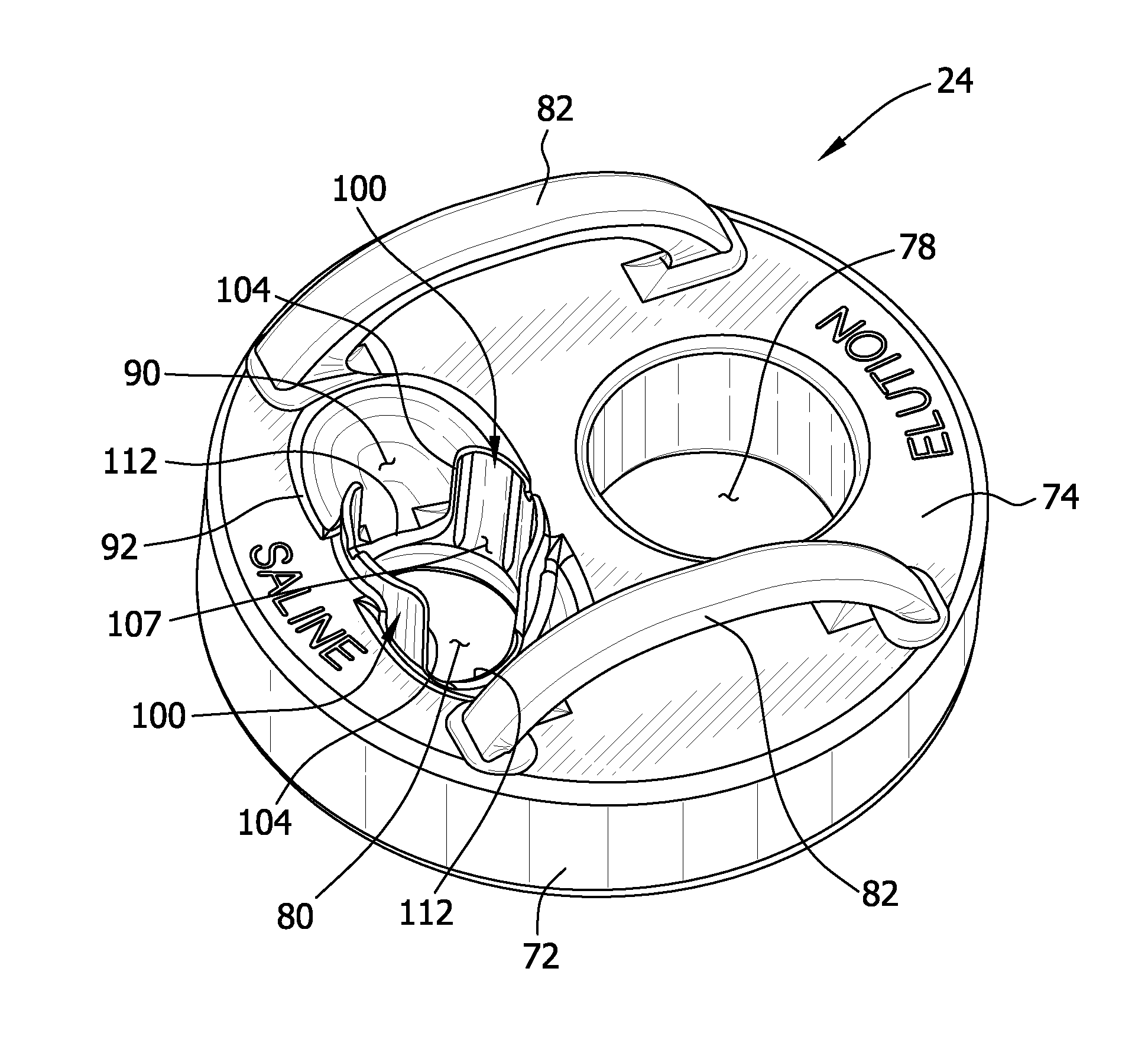
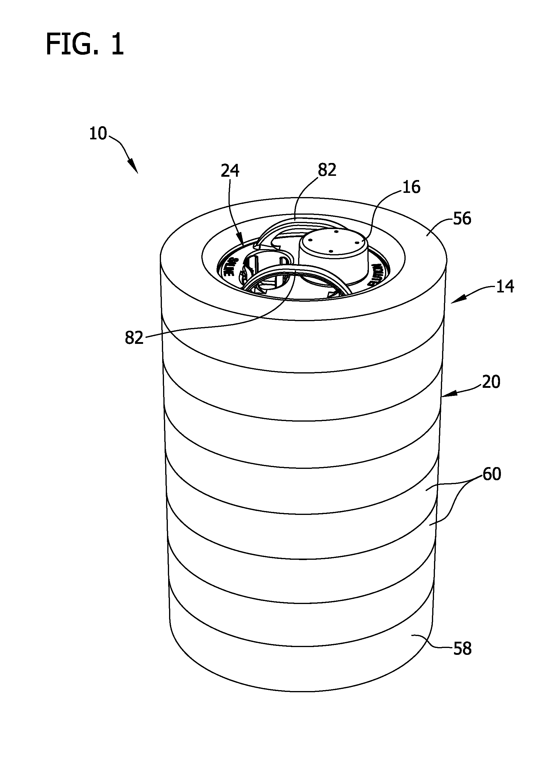
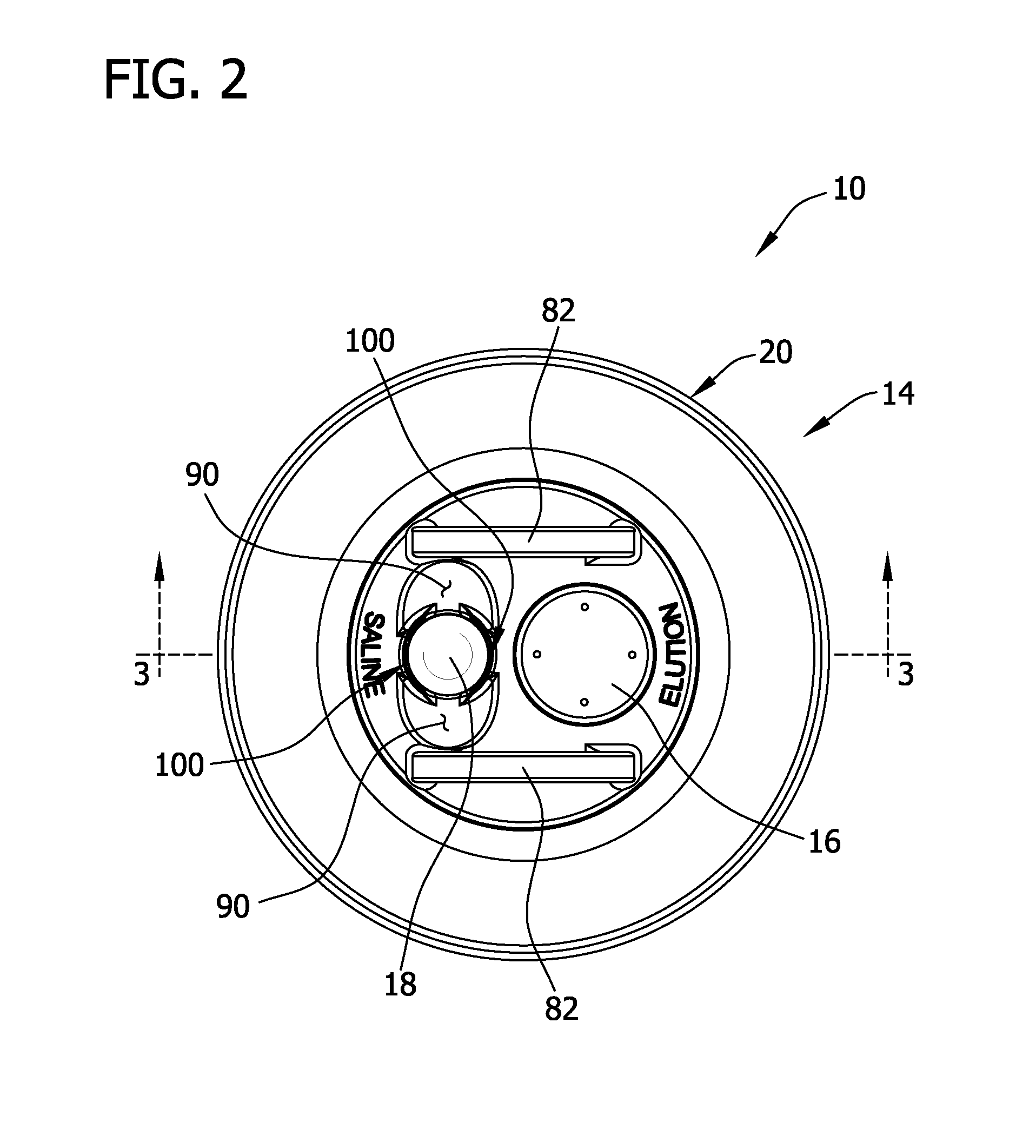
[0029]Referring to FIGS. 1-4, one embodiment of a radioisotope elution system 10 includes a radioisotope generator 12 (FIGS. 3 and 4), which is removably receivable in an auxiliary shield assembly 14. As explained in more detail below, an elution tool 16, which houses an elution vial 17 (broadly, a container), and an eluant vial 18 (broadly, a container) are fluidly connectable to the radioisotope generator 12. Herein, “fluidly connectable” refers to the ability of first component and a second component to be connected (either directly or indirectly) or interface in a manner such that fluid (e.g., eluate, eluant) may flow therebetween in a substantially confined flow path. The auxiliary shield assembly 14 includes a radiation shielding body 20 that defines a cavity 22 in which the generator 12 is removably receivable, and a radiation shielding lid 24 that may be positioned on the body 20 toward a top thereof to substantially enclose the cavity 22 defined in the body 20. In general, ...


PUM


Abstract

Disclosed herein are embodiments of a radiation shielding lid of a radiation shielding container (e.g., auxiliary radiation shield) designed to house a radioisotope generator assembly.

Description

CROSS-REFERENCE TO RELATED APPLICATION[0001]The present application is a continuation-in-part of U.S. patent application Ser. No. 29 / 383,507 filed Jan. 19, 2011, and having the title “Radiation Shielding Container Lid.”BACKGROUND[0002]The present disclosure relates generally to a radiation shielding lid for an auxiliary shield assembly of a radioisotope elution system.[0003]Nuclear medicine uses radioactive material for diagnostic and therapeutic purposes by injecting a patient with a dose of the radioactive material, which concentrates in certain organs or biological regions of the patient. Radioactive materials typically used for nuclear medicine include Technetium-99m, Indium-111, and Thallium-201 among others. Some chemical forms of radioactive materials naturally concentrate in a particular tissue, for example, radioiodine (I-131) concentrates in the thyroid. Radioactive materials are often combined with a tagging or organ-seeking agent, which targets the radioactive material f...

Claims


Application Information

Patent Timeline
IPC IPC(8): G21F3/00
CPCG21F5/015G21G1/0005G21F5/12
Inventor MAYFIELD, SCOTT HAYWARDMARTZ, KEVIN ROBERT
Owner CURIUM US LLC
Why Eureka
Try Eureka