Spectral Detection Device for Detecting Spectral Components of Received Light

Inactive Publication Date: 2012-07-26
SIGNIFY HLDG BV
View PDF10 Cites 11 Cited by
  • Summary
  • Abstract
  • Description
  • Claims
  • Application Information

AI Technical Summary

Benefits of technology

[0012]The filtering structure may be adapted to transmit light with a wavelength that lies within the predetermined wavelength range (while blocking light with a wavelength outside the predetermined wavelength range). As a transmissive filtering structure may simply be placed on top of the light sensor, it may be easily mounted in the spectral detection device and enables a compact arrangement.
[0013]According to an alternative embodiment, the filtering structure may be adapted to reflect light with a wavelength that lies within the predetermined wavelength range (while transmitting light with a wavelength outside the predetermined wavelength range). An advantage is that a reflective filtering structure in principle may be implemented using a single switchable photonic band gap filter.
[0014]According to an embodiment, the filtering structure may comprise a switchable photonic band gap filter.

Problems solved by technology

However, even though the spectral detection device disclosed in WO2008/012715 may satisfactorily measure the spectral components of received light, it is costly to deposit an array of multilayered interference filter

Method used


Image

  • Spectral Detection Device for Detecting Spectral Components of Received Light
  • Spectral Detection Device for Detecting Spectral Components of Received Light
  • Spectral Detection Device for Detecting Spectral Components of Received Light

Examples


Embodiment Construction

[0033]The present invention will now be described more fully hereinafter with reference to the accompanying drawings, in which currently preferred embodiments of the invention are shown. This invention may, however, be embodied in many different forms and should not be construed as limited to the embodiments set forth herein; rather, these embodiments are provided for thoroughness and completeness, and fully convey the scope of the invention to the skilled addressee. Like reference characters refer to like elements throughout.

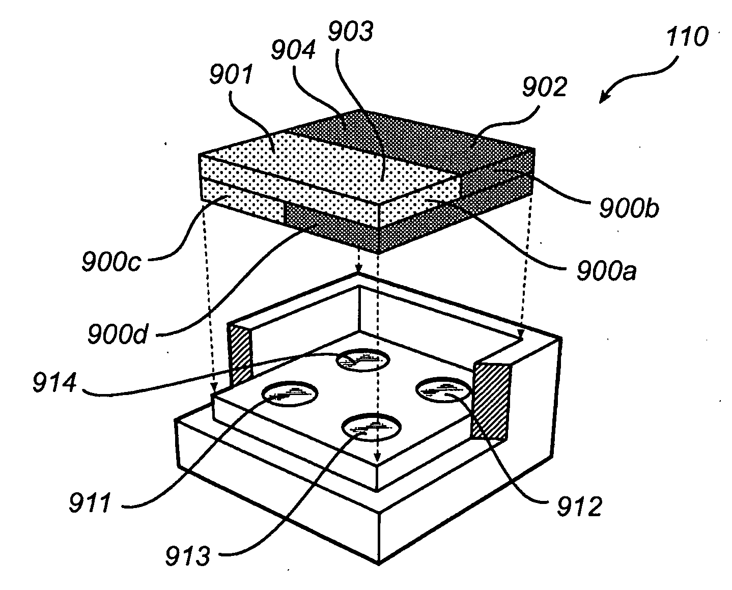
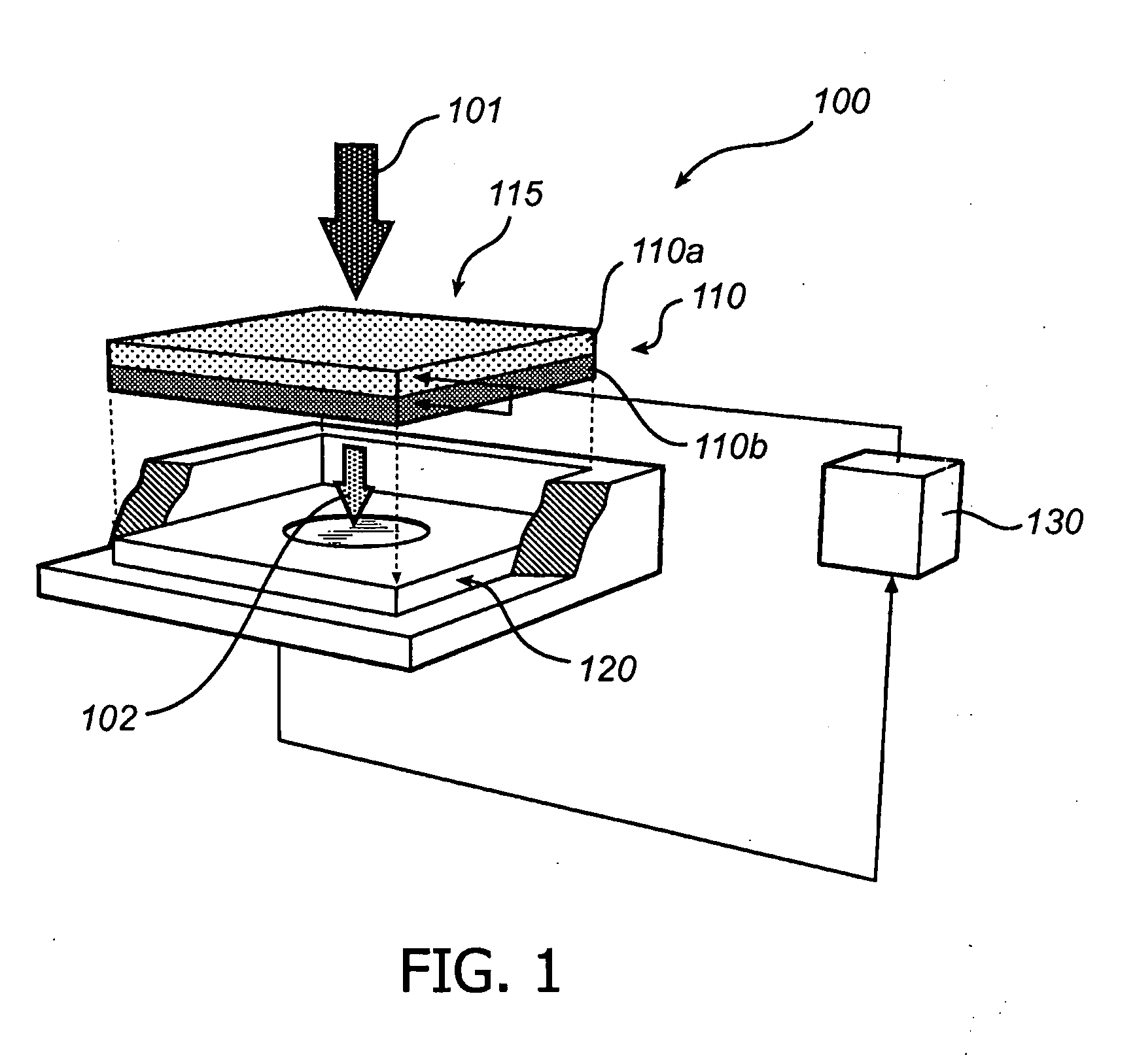
[0034]Referring now to the drawings and to FIG. 1 in particular, there is depicted a spectral detection device 100 according to an embodiment of the invention. The spectral detection device 100 comprises a light sensor 120 and a filtering structure 110 arranged between the light sensor 120 and a light inlet 115 of the spectral detection device. Here this is achieved by arranging the filtering structure 110 on top of the light sensor 120. The light sensor (or a ...


PUM


Abstract

The present invention relates to a spectral detection device (100) for detecting spectral components of received light, wherein the spectral detection device (100) comprises a filtering structure (110) arranged to filter the received light and output light with a wavelength within a predetermined wavelength range; and a light sensor (120) arranged to detect the light output by the filtering structure (110), wherein the filtering structure (110) is variable to allow a variation of the predetermined wavelength range over time.
The arrangement enables a compact spectral detection device that may be provided at a low cost.

Description

FIELD OF THE INVENTION[0001]The present invention relates to a spectral detection device for detecting spectral components of received light.BACKGROUND OF THE INVENTION[0002]Today spectral detection devices, such as spectrometers, are increasingly used in light management applications, for example, to measure the color point and color rendering index of light to determine the atmosphere created by a number of luminaries, and / or to monitor light emitted by a specific luminary.[0003]A typical example of a light management application using a spectrometer is an ambient intelligent lighting system that allows a user to flexibly determine the atmosphere created by a number of luminaries in a room. To achieve the desired atmosphere the ambient intelligent system measures and controls the lighting characteristics of each individual luminary by a control feedback system that measures the intensity, color point and color rendering index of the individual luminaries.[0004]Furthermore, a spect...

Claims


Application Information

Patent Timeline
IPC IPC(8): H05B37/02G01J3/51
CPCF21V23/0442F21Y2113/005G01J1/0266G01J1/0488G01J1/06G01J1/32G01J3/02G01J3/0205G01J3/0289G01J3/32G01J3/36G01J3/51G01J3/513G01J2003/1213G02B1/005G02B5/20G02B19/0066G02B19/0085G02B19/0028F21K9/137F21Y2101/02F21K9/233F21Y2115/10F21Y2113/13G01J3/12G02F1/19G01J3/28G01J2003/1282
Inventor HIKMET, RIFAT ATA MUSTAFAVAN BOMMEL, TIESMEIJER, EDUARD JOHANNES
Owner SIGNIFY HLDG BV
Why Eureka
Try Eureka